1. Theoretical basis for tube sheet calculation
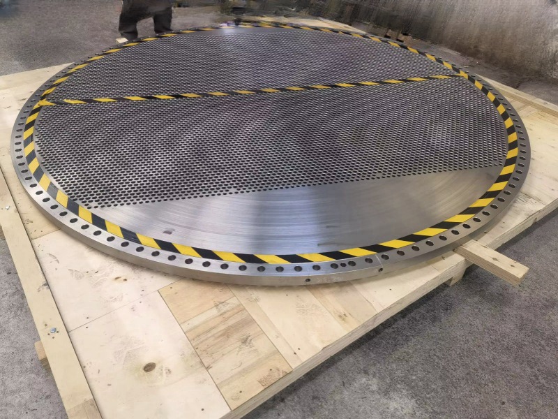
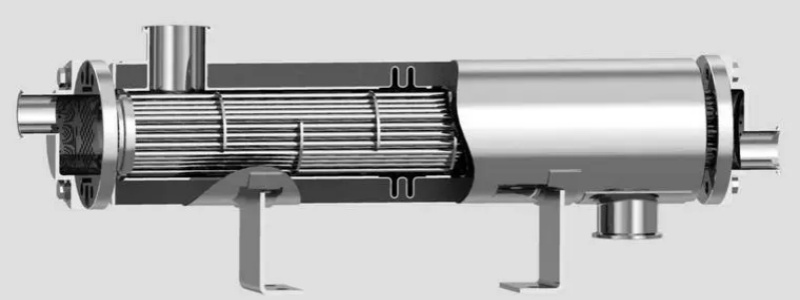
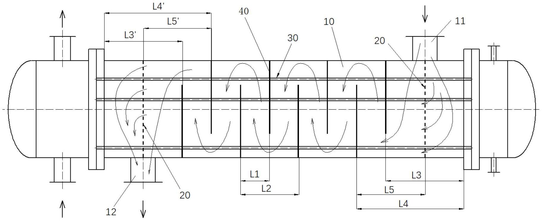
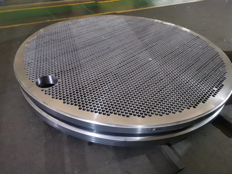
The structure of shell and tube heat exchangers is complex, and there are many factors that affect the strength of the tube sheet. In particular, the tube sheet of fixed tube sheet heat exchangers is subjected to the most complex force. The design specifications of various countries basically consider the tube sheet as a circular flat plate that bears uniformly distributed loads, is placed on an elastic foundation, and is uniformly weakened by the tube holes (Figure 1).

Due to the many factors that affect the strength of the tube sheet, it is difficult and complex to accurately analyze the strength of the tube sheet. Therefore, various countries simplify and assume the formula for calculating the thickness of the tube sheet to obtain an approximate formula.
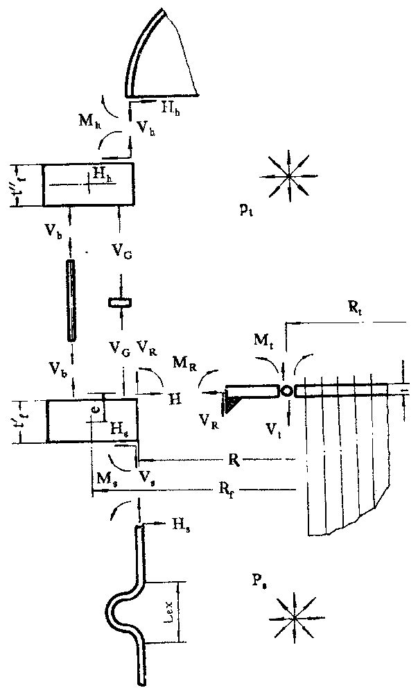
The loads that cause stress on the tube sheet include pressure (tube side pressure Pt, shell side pressure Ps), thermal expansion difference between the tube and shell, and flange torque. The mechanical model of the calculation method for the tube sheet of the heat exchanger is shown in Figure 2.
1.1 The design specifications of various countries consider the following factors to varying degrees for the tube sheets:
1) Simplifying the actual tube sheet into a homogeneous equivalent circular flat plate based on equivalent elasticity weakened by regular arrangement of tube holes and reinforced by tubes has been adopted by most countries' tube plate specifications today.
2) The narrow non piping area around the tube sheet is simplified as a circular solid plate based on its area.
3) The edge of the tube sheet can have various types of connection structures, which may include shell side cylinders, channel cylinders, flanges, bolts, gaskets, and other components. Calculate according to the actual elastic constraint conditions of each component on the edge of the tube sheet.
4) Consider the effect of flange torque on the tube sheet.
5) Consider the temperature difference stress caused by the thermal expansion difference between the heat exchange tube and the shell side cylinder, as well as the temperature stress caused by the temperature difference at various points on the tube sheet.
6)Calculate various equivalent elastic constants and strength parameters converted from porous plates with heat exchange tubes to equivalent solid plates.
1.2 Theoretical basis for GB151 tube sheet calculation
The mechanical model considers the tube plate as an axial symmetry structure and assumes that the tubesheets at both ends of the heat exchanger have the same material and thickness. For fixed tube sheet heat exchangers, the two tube sheets should also have the same boundary support conditions.
1) The supporting effect of tube bundle on tube sheet
Consider the tube sheet as an equivalent circular flat plate uniformly weakened and placed on an elastic foundation. This is because in the structure of shell and tube heat exchangers, the diameter of the majority of tubes is relatively small compared to the diameter of the tube sheet, and the number of tubes is sufficient. It is assumed that they are uniformly distributed on the tube sheet, so the support effect of each discrete heat exchange tube on the tube sheet can be considered uniform and continuous, and the load borne by the tube sheet is also considered uniformly distributed.
The tube bundle has a restraining effect on the deflection and rotation angle of the tube sheet under external loads. The restraining effect of the tube bundle can reduce the deflection of the tube sheet and lower the stress in the tube sheet. The tube bundle has a restraining effect on the angle of the tube sheet. Through analysis and calculation of actual parameters, it was found that the restraining effect of the tube bundle on the angle of the tube sheet has a very small impact on the strength of the tube sheet and can be completely ignored. Therefore, this
The specification does not consider the constraint effect of tube bundles on the corner of the tube sheet, but only considers the constraint effect of tube bundles on the deflection of the tube sheet. For fixed tube sheet heat exchangers, the tube reinforcement coefficient K is used to represent the tube sheet.
The bending stiffness of the perforated tube plate is η D
The elastic foundation coefficient N of the tube bundle represents the pressure load required to be applied on the surface of the tube plate to cause unit length deformation (elongation or shortening) of the tube bundle in the axial direction.
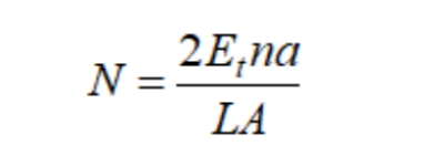
the pipe reinforcement coefficient K and substitute it into the expressions D and N, so that ν P=0.3:

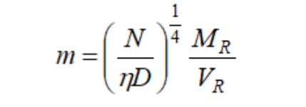
This coefficient indicates the strength of the elastic foundation relative to the tube plate's inherent bending stiffness, reflecting the enhanced load-bearing capacity of the tube bundle on the plate. It is a crucial parameter that characterizes the strengthening effect of the tube bundle on the plate. If the elastic foundation of the plate is weak, the enhancing effect of the heat exchange tubes is minimal, resulting in a small K value. Consequently, the plate's deflection and bending moment distribution resemble those of ordinary circular plates lacking an elastic foundation. Specifically, when K equals zero, the plate becomes an ordinary circular plate. Based on the theory of elastic foundation circular plates, the plate's deflection is not solely determined by the tube's strengthening coefficient K, but also by its peripheral support and additional loads, quantitatively represented by the total bending moment coefficient m.
When the periphery of the tube sheet is simply supported, MR=0, then m=0; When the periphery of the tube sheet is fixed, the corner of the edge of the tube sheet φ R=0, from which a specific value of m can be obtained (the expression is omitted); When the periphery of the tube plate only bears the action of bending moment, i.e. VR=0, then m=∞.
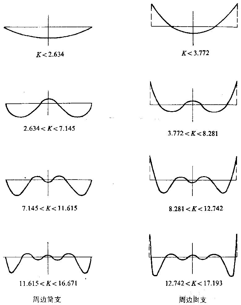
Under certain boundary support conditions, as the K value gradually increases, the deflection and bending moment of the tubesheet exhibit a attenuation and wavy distribution from the periphery to the center. The larger the K value, the faster the attenuation and the more wave numbers. During the process of increasing K value, when passing through a certain boundary K value, new waves will appear in the distribution curve. At the center of the plate, the curve changes from concave (or concave) to concave (or concave). Solving the derivative equation of the distribution curve can obtain the K boundary value of the curve with an increase in wave number.
Taking the simple support around the tube sheet as an example, as the strengthening coefficient K of the tube increases, the radial bending moment distribution curve and the boundary K value when new waves appear are shown in Figure 31. At the same time, it can be seen that the radial extreme value also moves away from the center of the tube sheet towards the periphery as the K value increases.
For the elastic foundation plate with peripheral fixed support, the radial bending moment distribution shows a similar trend with the change of K value, as shown in Figure 3. The difference from a simply supported boundary is that the maximum radial bending moment of the elastic foundation plate supported by a fixed boundary is always located around the circular plate, while the extreme point of the second radial bending moment moves away from the center of the plate and towards the periphery as K increases.
For floating head and filled box heat exchanger tube sheets, the modulus K of the tube bundle is similar to the elastic foundation coefficient N of the fixed tube sheet, which also reflects the strengthening effect of the tube bundle as an elastic foundation on the tube sheet.
2) The weakening effect of tube holes on tube sheets
The tube sheet is densely covered with dispersed tube holes, so the tube holes have a weakening effect on the tube sheet. The weakening effect of tube holes on the tube sheet has two aspects:
The overall weakening effect on the tube sheet reduces both the stiffness and strength of the tube sheet, and there is local stress concentration at the edge of the tube hole, only considering peak stress.
This specification only considers the weakening effect of openings on the overall tube sheet, calculates the average equivalent stress as the basic design stress, that is, approximately considers the tube sheet as a uniformly and continuously weakened equivalent circular flat plate. For local stress concentration at the edge of the tube hole, only peak stress is considered. But it should be considered in fatigue design.
The tube hole has a weakening effect on the tube sheet, but also considers the strengthening effect of the pipe wall, so the stiffness weakening coefficient is used η And strength weakening coefficient μ。 According to elastic theory analysis and experiments, this specification stipulates η and μ= 0.4.
3) Equivalent diameter of tube sheet layout area
The calculation of the reinforcement coefficient for fixed tube sheets assumes that all pipes are uniformly distributed within the diameter range of the cylinder. In fact, under normal circumstances, there is a narrow non pipe area around the tube sheet, which reduces the stress at the edge of the tube sheet.
The tube layout area is generally an irregular polygon, and now the equivalent circular pipe layout area is used instead of the polygonal pipe layout area. The value of the equivalent diameter Dt should make the supporting area of the tube on the tube sheet equal. The diameter size directly affects the stress magnitude and distribution of the tube plate. In the stress calculation of the fixed tube sheet in GB151, the stress located at the junction of the annular plate and the pipe layout area is approximately taken as the stress of the full pipe layout tube plate at a radius of Dt/2. Therefore, the standard limits this calculation method to only be applicable to situations where the non pipe layout area around the tube plate is narrow, that is, when the non dimensional width k of the non pipe layout area around the tube sheet is small, k=K (1)- ρ t) ≤ 1.
Whether it is a fixed tube sheet heat exchanger, or a floating head or filled box heat exchanger, when calculating the area of the tube layout area, it is assumed that the tubes are uniformly covered within the range of the tube layout area.
Assuming there are n heat exchange tubes with a spacing of S. For a triangular arrangement of tube holes, the supporting effect of each tube on the tube sheet is the hexagonal area centered on the center of the tube hole and with S as its inner tangent diameter, i.e;
For tubes with square arrangement of tube holes, the supporting area of each tube on the tube sheet is a square area centered on the center of the tube hole and with S as the side length, i.e. S2.
The tube sheet layout area is the area enclosed by connecting the supporting area of the outermost tube of the tube sheet, including the supporting area of the outermost tube itself.
For a single pass heat exchanger tube sheet with uniformly distributed heat exchange tubes, the supporting area of all n heat exchange tubes on the tube sheet is the area of the tube layout area.
4) Consider the bending effect of the tube sheet, as well as the tensile effect of the tube sheet and flange along their central plane.
5) Assuming that when the flange deforms, the shape of its cross-section remains unchanged, but only the rotation and radial displacement of the center of gravity around the ring section. Due to this rotation and radial displacement, the radial displacement at the connection point between the flange and the center surface of the tube sheet should be coordinated and consistent with the radial displacement along the center surface of the tube sheet itself.
6) Due to temperature expansion difference γ The axial displacement of the shell wall caused by the shell side pressure ps and the tube side pressure pt should be coordinated and consistent with the axial displacement of the tube bundle and tube sheet system around the tube sheet.
7) The corner of the tube sheet edge is constrained by the shell, flange, channel, bolt, and gasket system, and its corner should be coordinated and consistent at the connection part.
8) When the tube sheet is also used as a flange, the influence of flange torque on the stress of the tube sheet is considered. In order to ensure sealing, it is stipulated that the flange stress needs to be checked for the extended part of the tube sheet that also serves as a flange. At this time, when calculating the flange torque, it is considered that the tube sheet and flange jointly bear the external force moment, so the ground force moment borne by the flange will be reduced.
About us
Wuxi Changrun has provided high-quality tube sheets, nozzles, flanges, and customized forgings for heat exchangers, boilers, pressure vessels, etc. to many well-known petrochemical enterprises at home and abroad. Our customers include PetroChina, Sinopec, Chevron, Bayer, Shell, BASF, etc. Send your drawings to sales@wuxichangrun.com We will provide you with the best quotation and the highest quality products.
