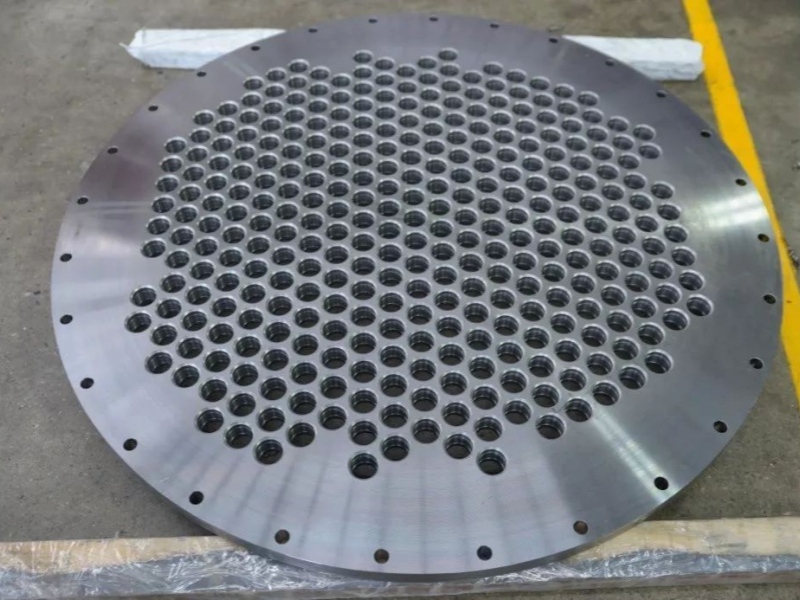
Shell and tube heat exchangers account for approximately 90% of the total amount of heat exchangers used in industry, making them the most widely used type of heat exchanger.
The typical structural forms of shell and tube heat exchangers include fixed tube sheet heat exchangers, U tube heat exchangers, floating head heat exchangers, stuffing box heat exchanger, kettle reboilers, double tube sheet heat exchangers, brace tube sheet heat exchangers, flexible tube sheet heat exchangers, and Spiral Wounded Heat Exchangers.
1. Fixed tube sheet heat exchanger
The fixed tube sheet heat exchanger (Figure 1) is a fixed connection (integral or clamped) between the two end tube sheets and the shell.
This is the most widely used type of heat exchanger. The two ends of the heat exchange tube are fixed on the tube sheet, which is welded to the shell.

Fixed tube sheet heat exchangers are suitable for various occasions:
1)In situations where the temperature difference between the metal on the tube and shell side is not very large and the pressure is high. When the temperature difference between the metal on the tube and shell side is large, the pressure cannot be too high because the large temperature difference will inevitably increase the expansion joint, which has poor pressure resistance.
2) Due to the inability of the shell side to be mechanically cleaned, it is required that the shell side medium be clean; Or in situations where scaling may occur but can be removed through chemical cleaning.
Advantages:
1) It has a simple structure, less use of forgings, and low manufacturing cost.
2) The tube side can be divided into various forms of multiple passes, and the shell side can also be divided into two passes.
3) The heat transfer area is 20% to 30% larger than that of a floating head heat exchanger.
4) The bypass leakage is relatively small.
Disadvantages:
1) Not suitable for situations where there is a significant difference in thermal expansion deformation between heat exchange tubes and shell side cylinders, as temperature difference stress can easily occur between the tube sheet and tube end, leading to damage.
2) After the corrosion of the pipe, it leads to the scrapping of the shell, and the lifespan of the shell components is determined by the lifespan of the pipe, so the equipment lifespan is relatively low.
3) The shell cannot be cleaned and inspection is difficult.
2. U-shaped tube heat exchanger
The U-shaped tube heat exchanger (Figure 2) is a heat exchange tube with two ends fixed on the same tube plate, which is fixedly connected to the shell (integral or clamped).

U-shaped tube heat exchangers can be used in the following situations
1) The flow in the pipeline is clean fluid.
2) The pressure in the pipeline is particularly high.
3) In situations where there is a large temperature difference between the metal on the tube and shell sides, and fixed tube plate heat exchangers cannot even meet the requirements with expansion joints.
Advantages:
1) The free floating at the end of the U-shaped heat exchange tube solves the temperature difference stress and can be used for two media with large temperature differences. The temperature difference between the metal on the tube and shell side is not limited.
2) The tube bundle can be pulled out to facilitate frequent cleaning of the outer wall of the heat exchange tube.
3) With only one tube plate and a small number of flanges, the structure is simple and there are few leakage points, resulting in a lower cost.
4) It can work under high temperature and high pressure, and is generally suitable for t ≤ 500 ℃ and p ≤ 10MPa.
5) Can be used in situations where shell side scaling is relatively severe.
Disadvantages:
1) When the flow rate in the pipe is too high, it will cause serious erosion on the U-shaped bend section, affecting its service life. Especially for pipes with low R, the flow rate inside the pipe should be controlled.
2) The pipeline is not suitable for situations with heavy scaling.
3) Due to the limitation of u-tube Rmim and wide separation distance, the number of tubes in the fixed tube sheet heat exchanger is slightly less.
4) When the heat exchange tube leaks, except for the outer U-shaped tube, it cannot be replaced and can only be blocked.
5) The central part of the tube bundle has large pores, and the fluid is prone to short circuits, which affects the heat transfer effect. Therefore, partitions should be added to reduce short circuits.
6) Due to the large dead zone, it is only suitable for the inner guide tube.
7) The number of heat exchange tubes arranged on the tube plate is relatively small.
8) The U-shaped bending section of the outermost pipe, due to its large unsupported span, should cause fluid induced vibration problems.
9) When there are requirements for stress corrosion, careful consideration should be given.
3. Floating head heat exchanger
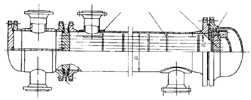
The floating head heat exchanger (Figure 3) is a clamped type where one end of the tube sheet is fixedly connected to the shell, while the other end of the floating head tube sheet (including the floating head cover, backing device, etc.) floats freely inside the tube box. Therefore, there is no need to consider temperature difference stress, as there is a large temperature difference between the metal walls of the tube and shell sides.
Advantages:
1) The tube bundle can be pulled out for easy cleaning of the tube and shell side.
2) The shell wall and tube wall are not limited by temperature difference.
3) It can work under high temperature and high pressure, generally t ≤ 450 ℃ and p ≤ 6.4MPa.
4) Can be used in situations with severe scaling.
5) Can be used in pipeline corrosion scenarios.
Disadvantages:
1) It is difficult to take measures when leakage occurs during the operation of the floating head sealing surface inside the shell side medium.
2) Complex structure, high metal material consumption, and high cost.
3) The floating head structure is complex and affects the number of pipes arranged.
4) The pressure test fixture used during pressure testing is complex.
5) Metal materials consume a large amount and have a 20% higher cost.
stuffing box heat exchanger
One end of the tube sheet is fixedly connected to the shell (clamp type), while the other end of the tube sheet floats freely inside the packing box.
The tube bundle can be extended and can be used for two media with a large temperature difference. The structure is also simpler than that of a floating head, making it easier to manufacture and more cost-effective than a floating head heat exchanger. Because the tube bundle can be pulled out, it is easy to maintain and clean. Suitable for use in media with severe corrosion.
4.1 Outside packed heat exchanger (Figure 4)
Suitable for equipment with a diameter below DN700mm, and the operating pressure and temperature should not be too high. It is generally used in situations where p ≤ 2.0MPa.

4.2 Sliding tube sheet packing box heat exchanger
At the sealing point on the inner side of the packing, there will still be a flow phenomenon etween the medium on the tube and shell side, which is not suitable for situations where the medium on the tube and shell side is not allowed to mix.
4.2.1 Single stuffing box heat exchanger (Figure 5)
At the sealing point on the inner side of the packing, there will still be a flow phenomenon between the medium on the tube and shell side, which is not suitable for situations where the medium on the tube and shell side is not allowed to mix.
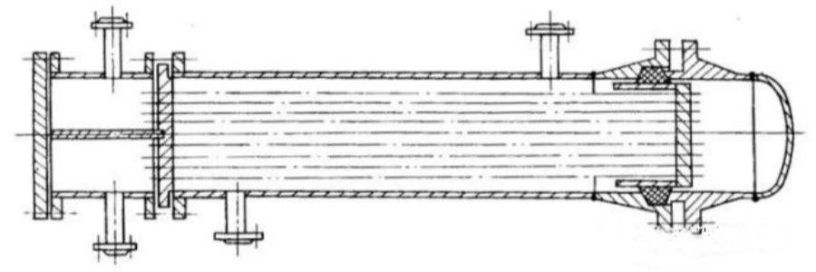
4.2.2 Double stuffing box heat exchanger (Figure 6)
The structure is mainly sealed with the inner ring to prevent internal and external leakage, while the outer ring is used as an auxiliary seal to prevent external leakage. A leakage outlet pipe is set between the inner and outer sealing rings to connect with the low-pressure vent main. This structure can be used for medium with moderate harm, explosive and other media.
5. Kettle reboiler
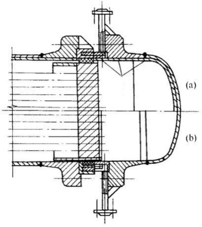
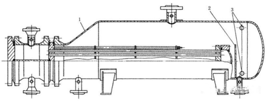
The kettle reboiler (Figure 7) is a fixed connection (clamp type) between one end of the tube sheet and the shell, and the other end is a U-shaped or floating head tube bundle. The shell side is a single (or double) inclined cone shell with evaporation space, so the temperature and pressure on the tube side are higher than those on the shell side. Generally, the shell side medium is heated by the tube side medium. P ≤ 6.4 MPa.
Advantages:
1) Suitable for bottom reboilers and side line siphon reboilers.
2) Save over 25% of equipment weight.
3) Good corrosion resistance.
4) It has a self-cleaning effect. In situations where there is a large temperature difference between the tube and shell side.
5) The total heat transfer coefficient has increased by more than 40%.
6) In situations with high vaporization rates (30-80%).
7) In situations where the liquid phase of the reboiled process medium is used as a product or requires high separation requirements.
8) Good corrosion resistance.
Disadvantages:
1) On heavy oil equipment, such as residual oil and crude oil equipment, there is no application history.
2) Not suitable for environments with wet hydrogen sulfide.
6.Double tube sheet heat exchanger
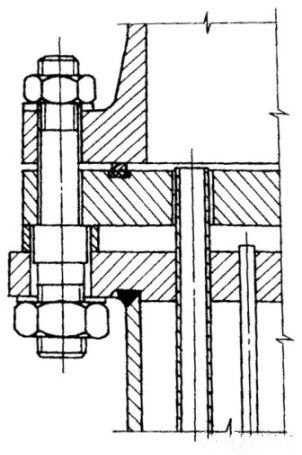
The double tube sheet heat exchanger (Figure 8) has two tube sheets on each side, and one end of the heat exchange tube is connected to both tube sheets simultaneously. Mainly used for mixing the medium between the tube side and shell side, which will result in serious consequences. But manufacturing is difficult; High design requirements.
1) Corrosion prevention: Mixing the two media of the tube side and shell side can cause severe corrosion.
2) Labor protection: One route is a highly toxic medium, and infiltration into the other route can cause extensive system pollution.
3) In terms of safety, mixing the medium on the tube side and shell side can cause combustion or explosion.
4) Equipment contamination: Mixing of tube side and shell side media can cause polymerization or the formation of resin like substances.
5) Catalyst poisoning: The addition of another medium can cause changes in catalyst performance or chemical reactions.
6) Reduction reaction: When the medium on the tube side and shell side is mixed, it causes the chemical reaction to terminate or limit.
7) Product impurity: When the medium in the tube and shell is mixed, it can cause product contamination or a decrease in product quality.
6.1 Double tube sheet fixed tube sheet heat exchanger (Figure 9)

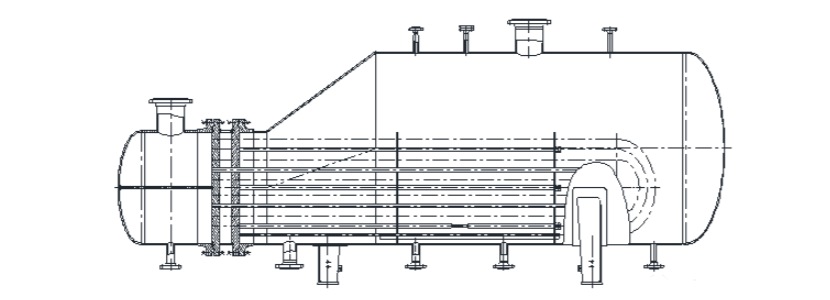
6.2 Double tube plate U-tube heat exchanger (Figure 10)

6.3 Double tube U-tube kettle reboiler (Figure 11)
7.Pulling tube sheet heat exchanger
The pull-up tube sheet heat exchanger (Figure 12) has a thinner tube plate thickness, usually between 12 and 18mm.

7.1 The structural types include:
(1) Face to face (Germany): The tube sheet is welded onto the sealing surface of the equipment flange (Figure 12a).
(2) Inlaid type (former Soviet Union) ГОСТ Standard): The tube sheet is welded to the flat surface of the equipment flange sealing surface (Figure 12b).
(3) Corner welding (formerly developed by Shanghai Pharmaceutical Design Institute): The tube sheet is welded to the shell (Figure 12c).
7.2 Scope of application:
1) Design pressure: The tube side and shell side shall not exceed 1.0 MPa respectively;
2) Temperature range: The design temperature range for the tube side and shell side is from 0 ℃ to 300 ℃; The average wall temperature difference between the heat exchange tube and the shell shall not exceed 30 ℃;
3) Diameter range: The inner diameter of the shell shall not exceed 1200mm;
4) Heat exchange tube length: not exceeding 6000mm.
5) Heat exchange tubes should be made of light tubes and have a linear expansion coefficient close to that of the shell material (the difference in values between the two should not exceed 10%).
7.3. Expansion joints should not be installed.
8. Flexible tube sheet heat exchanger
Suitable for horizontal shell and tube residual (waste) heat boilers with gas as the medium on the tube side and saturated water vapor generated on the shell side.
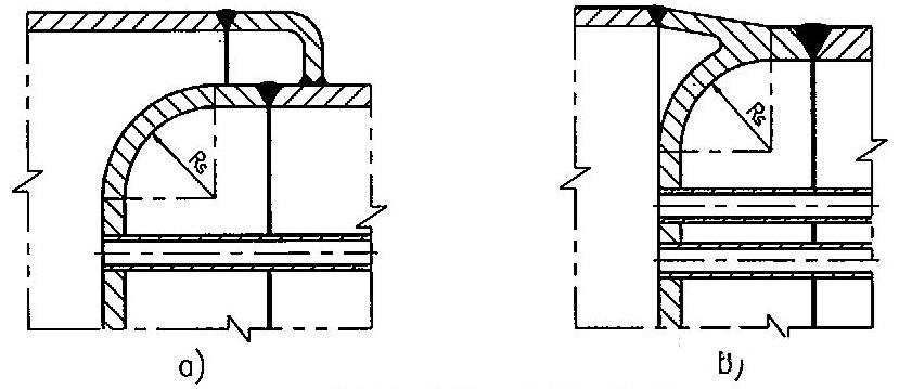
The connection between Type I tube sheet and shell (channel) (see Figure 13a) and the connection between Type II tube sheet and shell (channel) (see Figure 13b).
Applicable scope:
1) The design pressure of the tube side shall not exceed 1.0 MPa, the design pressure of the shell side shall not exceed 5.0 MPa, and the shell side pressure shall be greater than the tube side pressure;
(1) Type I is used for pipe design pressure less than or equal to 0.6MPa;
(2) Type II is used for piping design pressures less than or equal to 1.0 MPa.
2) The diameter of the shell and the length of the heat exchange tube are 2500mm and 7000mm, respectively.
9. Efficient spiral wounded tube heat exchanger
In order to save equipment investment, the maximum heat transfer area of heat exchange tubes is arranged within the limited shell volume of the heat exchanger, and the heat transfer efficiency is improved. Therefore, the shell and tube wound tube heat exchanger (Figure 16) has emerged. This type of heat exchanger is a multi-layer multi head stainless steel small diameter heat exchange tube wound and welded on the core rod, as shown in Figure 16.

10. Austenitic stainless steel corrugated heat exchanger
1) Applicable scope:
(1) The design pressure shall not exceed 4.0MPa;
(2) The design temperature shall not exceed 300 ℃;
(3) The nominal diameter shall not exceed 2000mm;
(4) The nominal diameter shall not exceed 4000 times the product of the design pressure.
2) Inappropriate occasions
(1) Media with extreme or highly hazardous toxicity;
(2) Explosive media;
(3) In situations where there is a tendency towards stress corrosion.
Wuxi Changrun has provided high-quality tube sheets, nozzles, flanges, and customized forgings for heat exchangers, boilers, pressure vessels, etc. to many well-known petrochemical enterprises at home and abroad. Our customers include PetroChina, Sinopec, Chevron, Bayer, Shell, BASF, etc. Send your drawings to sales@wuxichangrun.com We will provide you with the best quotation and the highest quality products.
