Does A Ball Valve Need to be Fully Open?

A ball valve does not always need to be fully open, but whether it should be fully open or not depends on the application and the design of the valve.

1. Designed for On/Off Control

Ball valves are typically designed for full on/off control, meaning they function best when they are either fully open or fully closed. This is because they allow for minimal resistance to flow when fully open and provide a complete seal when fully closed. Operating a ball valve in a partially open position for extended periods can lead to issues like:

(1) Turbulent Flow: Partial opening can create turbulence, increasing wear on the valve and pipe.

(2) Damage to the Ball and Seals: The high velocity and turbulence near the partially open ball can cause damage to the sealing surfaces.

(3) Vibration and Noise: A partially open ball valve may cause vibration or noise due to the irregular flow.


2. Throttling Applications

Although ball valves are primarily used for on/off applications, they can be used for throttling (controlling flow) in certain cases. However, for precise flow control, globe valves or other throttling valves are more suitable because they are designed to handle partial openings without causing damage to the valve or creating inefficiencies in flow control.


3. Special Ball Valves for Throttling

Some ball valves are specifically designed with V-port balls or multi-port designs, which allow for better flow control when partially open. These valves provide more precise control over the flow compared to standard ball valves and can be safely used in a partially open position.


While a ball valve can operate in a partially open position, it is generally recommended to use it fully open or fully closed for optimal performance and longevity, unless it is a specialized ball valve designed for throttling. For precise flow regulation, other types of valves may be more appropriate.

What is the Best Valve for a Gas Line?

In the installation and maintenance of gas systems, selecting the appropriate valve is crucial for both safety and performance. Given the characteristics of gas and its application environments, ball valves and gate valves are widely recommended as ideal choices for gas pipelines due to their excellent sealing performance and ease of operation. However, their specific characteristics, suitable applications, and considerations for installation and maintenance differ. The following provides a detailed analysis of the advantages and disadvantages of these two valves, as well as the gas system scenarios in which they are best suited.


1. Ball Valve: Precise Control and Quick Shut-off


(1) Quick Opening and Closing Operation

The design of the ball valve allows for rapid opening or closing, which is especially crucial for emergency control in gas pipelines. By simply rotating the handle 90 degrees, the gas flow can be quickly cut off, making it highly effective in handling emergencies such as leaks.


(2) Reliable Sealing Performance

The ball valve opens and closes through the rotation of its spherical element. When closed, a tight seal forms between the ball and the valve seat, reducing the risk of gas leakage. This sealing advantage is particularly prominent in high-pressure pipelines, where the ball valve can effectively ensure system safety.


(3) Corrosion Resistance and Broad Applicability

Ball valves used in gas pipelines are often made of materials such as stainless steel and brass, offering strong corrosion resistance and suitability for various gas types, including natural gas and liquefied gas. Whether in outdoor exposed environments or enclosed indoor settings, the materials and design of ball valves ensure their durability and stability.


(4) Low Maintenance Cost

The simple structure of ball valves results in minimal wear and low maintenance requirements, making them suitable for long-term use. Particularly in commercial and industrial pipeline systems, the low-maintenance nature of ball valves can reduce downtime and enhance cost-effectiveness.

These characteristics make ball valves a preferred choice for residential, commercial, and industrial gas distribution systems.


2. Gate Valve: Suitable for Flow Control in Long-Distance Pipelines


The gate valve controls flow through a rising and lowering gate mechanism. Unlike ball valves, gate valves open and close more slowly, making them more suitable for applications where frequent operation is not required.


(1) Suitable for Flow Regulation in Long-Distance Pipelines

When fully open or fully closed, the internal passage of the gate valve is nearly unobstructed, reducing pressure drop within the pipeline. This is particularly important for long-distance gas pipelines, as it helps maintain stable pressure and flow rate over extended distances.


(2) Gradual Opening and Closing to Reduce Pressure Shock

During closure, the gate valve gradually lowers the gate, making it suitable for pipeline systems that require controlled flow variation. This gradual operation effectively reduces the impact of fluid on the valve and pipeline, extending the system's service life.


(3) Versatile Pressure Ratings for Flexible Application

Gate valves are suitable for gas pipelines with various pressure ratings, meeting diverse flow requirements. Whether in low-pressure residential pipelines or high-pressure industrial systems, gate valves can provide relatively stable control.


3. How to Choose the Right Valve?


(1) Quick Switching and Emergency Handling

If a gas pipeline requires rapid opening or emergency shutdown, such as in response to a gas leak or emergency situation, a ball valve is more suitable.


(2) Stable Flow Control and Long-Distance Transportation

If a gas pipeline requires gradual flow control, such as in adjusting pressure variations during long-distance transportation, a gate valve is the better choice.


(3) Characteristics of Different Gases

Select suitable materials based on the corrosiveness and flammability of the specific gas to ensure the durability and safety of the valve.

When Plug Valve is Used?

The plug valve, with its simple structure and excellent sealing performance, has a wide range of applications in industrial fields. Its plug design allows for quick and safe opening and closing, making it suitable for numerous operating conditions that require strong sealing, high corrosion resistance, or frequent operation.

1. Applications Requiring High Sealing Performance

The plug valve excels in applications that require high sealing performance due to its unique design. The plug inside the valve body fits tightly, and the sealing material between the plug surface and the valve seat further enhances the sealing effect, effectively preventing leakage of the media. Many plug valves use high-performance sealing materials, such as polytetrafluoroethylene (PTFE), which are resistant to corrosion, making them suitable for transporting high-pressure and highly corrosive media in industries like oil and gas and chemicals.


(1) High Pressure Sealing Requirements in the Oil and Gas Industry

In oil and gas pipelines, the transportation of high-pressure, high-temperature gases or liquids is common, and any leakage could result in serious safety incidents. The plug valve, with its ability to quickly close and provide effective sealing, is an ideal choice for preventing leaks and ensuring the safety of the transportation process.


(2) Transportation of Volatile or Toxic Media

The sealing capability of the plug valve also makes it suitable for transporting volatile or toxic liquids and gases. Especially in fine chemicals and petrochemical production, preventing the leakage of volatile chemicals is a core aspect of safety. The sealing structure of the plug valve is perfectly suited to meet this requirement.


2. Frequent Opening and Closing Operations

The plug valve only requires a 90-degree rotation to open or close, making the operation simple and fast, while reducing mechanical wear. This makes the plug valve suitable for applications with frequent on/off cycles. In chemical plant production processes, valves are often required to open and close frequently to regulate fluid flow. Compared to other valves, the plug valve's opening and closing mechanism is more stable, which helps to extend its service life.


(1) Impact of Frequent Operation on Equipment

In environments where frequent operation is required, improper handling can lead to increased valve wear and a higher probability of leakage. Due to its simple structure and fewer components, the plug valve is less affected by frequent operations, offering significant economic benefits in this regard.


3. Applications with High Corrosion Resistance Requirements

Plug valves are typically made from corrosion-resistant materials, and their interiors are often lined with corrosion-resistant materials such as PTFE or reinforced plastics, allowing them to maintain long-term operation when handling acidic, alkaline, or corrosive solutions. Plug valves are particularly well-suited for the transportation of highly corrosive liquids.


(1) Transporting Corrosive Media in the Chemical Industry

In the chemical industry, the media being transported often have strong corrosive properties. The design of plug valves ensures that they do not fail quickly when in contact with corrosive liquids, effectively reducing the frequency of equipment replacement and saving on maintenance costs.


4. Emergency Systems Requiring Quick Shutoff

The quick open/close design of the plug valve allows it to rapidly shut off the fluid passage in emergency situations, making it an ideal choice for preventing accidents and ensuring the safety of operators. For example, in emergency shutdown systems for natural gas pipelines and chemical plants, the plug valve can achieve a complete closure in an instant, preventing the leakage of hazardous substances and ensuring safety.


(1) Safety Requirements in the Natural Gas and Petrochemical Industries

In the natural gas and petrochemical industries, where high-temperature and high-pressure environments are common, safety is of utmost importance. The plug valve is not only easy to operate but also capable of quickly shutting off in emergencies, thereby protecting the overall safety of the system and reducing potential safety risks.


5. Medium and Low Pressure Fluid Transportation Systems

In medium and low pressure fluid transportation systems, the plug valve is an economical and practical choice. Its simple design reduces installation and maintenance complexity, and in situations where high-precision flow control is not required, the cost-effectiveness of the plug valve stands out. It is commonly found in systems such as water treatment, municipal water supply, and general industrial pipelines.


(1) Municipal Water Supply and General Industrial Applications

In municipal water supply systems, plug valves are widely used for flow control. Compared to more complex control valves, the plug valve features a simple structure and easy installation, making it suitable for fluid control applications that do not require high precision, while also being easier to maintain.

Why Do We Use a Gate Valve?

Gate valves are a popular choice in many industries for specific types of applications. Here’s why they are commonly used:


1. Full Flow or Isolation

Gate valves are ideal for situations where a full, unobstructed flow or complete shutoff is required. When fully opened, the gate valve allows fluid to pass through with minimal restriction, which helps to reduce pressure loss. This makes them particularly useful in systems where flow efficiency is critical, such as pipeline systems in oil, gas, and water distribution.


2. Low Pressure Drop

Because the gate in the valve fully retracts, there is little interference with the fluid flow when the valve is open. This results in low pressure drop, which is essential in applications where maintaining high flow efficiency is important, such as in petroleum refining or water treatment plants.


3. Versatility Across Applications

Gate valves can handle a wide range of fluids, including liquids, gases, and even slurry or other more viscous materials. They are also used in a variety of pressure and temperature conditions, making them highly versatile. This versatility is why they are found in industries such as chemical processing, mining, and power generation.


4. Bi-Directional Sealing

Gate valves can provide a tight seal in both directions, meaning they can effectively stop flow from either side of the valve. This feature makes them suitable for applications that require flow isolation from both ends, ensuring safety and operational control, especially in critical systems like offshore platforms and high-pressure pipelines.


5. Durability in Large-Scale Systems

Gate valves are particularly durable when used in large-diameter piping systems. Due to their robust design, they can handle the stresses of large-scale industrial applications, such as those found in hydropower or municipal water systems. Their ability to withstand high-pressure and high-temperature conditions adds to their durability and reliability.


6. Emergency Shutoff

Gate valves are often used as emergency shutoff valves because of their ability to completely block flow when needed. In situations where quick and reliable isolation is required, such as firefighting systems or hazardous material pipelines, gate valves offer peace of mind.

Why Does the Ball Valve Leak?

Ball valves are widely used in various industrial sectors due to their simple structure, excellent sealing performance, and ease of operation. However, during long-term use, ball valves may develop leaks. Leaks not only lead to the waste of media but can also disrupt the normal operation of the system and even pose safety risks.
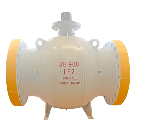
Common Reasons

1. Aging or Damage of Sealing Materials

The sealing performance of a ball valve primarily relies on the tight fit between the valve seat and the ball. These sealing components are typically made from materials such as rubber or polytetrafluoroethylene (PTFE). Over long-term use, the sealing materials may experience aging, deformation, or damage due to medium corrosion, high-temperature and high-pressure environments, or friction, leading to leaks. This issue is particularly common in applications involving high temperatures and highly corrosive media.


2. Wear of the Ball or Seat

The core components of a ball valve are the ball and the seat, which continuously contact and rub against each other during opening and closing. If the medium contains solid particles, or if the ball valve operates for an extended period in high-pressure, high-flow environments, wear can occur on the surfaces of the ball and seat. Worn surfaces struggle to form a tight seal with the sealing components, leading to inadequate sealing and resulting leaks.


3. Seal Failure of the Stem

The operation of a ball valve is facilitated by the stem, which connects to the valve body through the packing gland, providing a sealing function. Due to frequent operation, aging of the packing, or improper installation, the packing gland may experience seal failure, allowing the medium to leak along the stem. This type of leak is classified as external leakage, which can lead to environmental pollution and energy waste.


4. Improper Installation

If a ball valve is not correctly installed or tightened at the flange or threaded connections, gaps may occur, leading to leaks. Additionally, if factors such as thermal expansion and vibration of the pipeline are not considered during installation, the ball valve may experience stress during operation, resulting in leakage at the interface between the valve body and the pipeline.


5. Medium Factors

Certain special media, such as high-temperature, high-pressure fluids, highly corrosive substances, or fluids containing suspended particles, can accelerate the wear and corrosion of ball valves, leading to leaks. For example, acidic media can hasten the corrosion of metal components, while particulate matter may cause wear on the seat and ball, both of which can diminish the sealing performance of the ball valve, ultimately resulting in leakage issues.


How to Prevent and Handle

1. Choose Appropriate Sealing Materials

Selecting the right sealing materials for different operating conditions is crucial. For example, in high-temperature environments, high-temperature resistant sealing materials should be chosen, while chemical-resistant seals are necessary for highly corrosive media. Regular inspection and replacement of seals can also effectively prevent leaks caused by aging or wear.


2. Regular Maintenance and Care

Routine maintenance and regular servicing of ball valves help extend their lifespan and reduce the risk of leaks. The wear of the ball and seat should be regularly checked, and impurities and particles in the medium should be promptly removed to prevent further wear. Additionally, the packing should be inspected to ensure good sealing, and aging packing should be replaced in a timely manner.


3. Proper Installation and Operation

Installation should strictly adhere to the technical specifications of the ball valve, ensuring that flange or threaded connections are tight to avoid leaks caused by thermal expansion, vibration, or stress. Additionally, during operation, frequent opening and closing should be avoided, especially under high-pressure conditions, to reduce wear on the valve.


4. Special Treatment for Media

For applications involving fluids with suspended particles or strong corrosive properties, it is advisable to install a filter upstream of the ball valve to reduce solid particle damage to the valve. Additionally, choosing ball valves made from corrosion-resistant materials can effectively slow down the corrosion process and lower the risk of leakage.

Why is a Gate Valve More Widely Applicable Than a Ball Valve?

A gate valve is considered better than a ball valve in certain applications due to its design and functional advantages in specific conditions. Here are some key reasons why a gate valve might be preferred over a ball valve:


1. Flow Control

Gate Valve: Designed for full, unobstructed flow when fully open, allowing fluids to pass with minimal resistance. It is ideal for on-off control but not as suitable for throttling or flow regulation, as partial opening can cause vibration and damage to the sealing surfaces.

Ball Valve: While it offers full flow similar to a gate valve when open, it is not generally used for precise flow control either. However, it closes and opens faster than a gate valve, which may not always be ideal for systems that require gradual control of flow.


2. Size Availability

Gate Valve: Typically better for larger diameter applications, as they are available in larger sizes, making them suitable for large pipelines in industries like water treatment, oil, and gas.

Ball Valve: More commonly used in smaller pipe sizes but can also be found in larger sizes. However, large ball valves can become bulky and expensive compared to gate valves.


3. Pressure Drop

Gate Valve: When fully open, the gate valve provides a straight flow path with minimal pressure drop, which is beneficial in applications where maintaining fluid pressure is critical.

Ball Valve: Even though a ball valve offers low resistance to flow when fully open, the pressure drop might be slightly higher due to the internal mechanism of the ball and seat, especially in smaller sizes.


4. Cost Efficiency in Larger Systems

Gate Valve: More economical for large-diameter and high-pressure systems, making it a preferred choice in large-scale applications like water supply systems or oil pipelines.

Ball Valve: Generally more expensive for large diameters, as the ball itself and its seat must be designed to handle high pressures without deforming.


5. Operational Effort

Gate Valve: Requires more time and effort to open and close fully, as the gate needs to travel vertically through the fluid. This can be a disadvantage in situations where fast operation is needed but may be an advantage in preventing water hammer.

Ball Valve: Opens and closes quickly with a 90-degree turn, which is more convenient for applications requiring rapid shutoff. However, this quick action may cause issues like water hammer in some fluid systems.


6. Maintenance and Wear

Gate Valve: Due to its simple design, gate valves are easier to maintain and have a longer lifespan in systems where they are rarely operated. The seating surfaces experience less wear when the valve is either fully open or fully closed.

Ball Valve: The sealing surfaces in ball valves are more prone to wear, especially in high-pressure or abrasive flow conditions. Maintenance can be more complex, particularly with large valves.


7. Suitability for Dirty Fluids

Gate Valve: More suitable for handling fluids containing solids or slurries, as the gate can cut through debris or sediments. It is less prone to clogging in such environments.

Ball Valve: Not ideal for dirty or viscous fluids, as the tight tolerances between the ball and seat can trap particles, leading to damage or failure of the valve over time.

Elaborate on the Advantages and Limitations of Heating Jacket Gate Valves

The Heating Jacket Gate Valve is widely used in industries such as petrochemical, chemical, and pharmaceutical. Its primary function is to maintain the temperature of the valve and its internal fluid by circulating a heating medium within the jacket, preventing the fluid from solidifying or freezing due to temperature drop.

1. Advantages of the Heating Jacket Gate Valve

(1) Maintaining Fluid Temperature

The heating jacket gate valve maintains the temperature of the valve body and internal fluid through the heating medium circulating within the jacket (such as steam, hot oil, etc.), preventing the medium from solidifying or freezing due to temperature drop. This is particularly important for high-viscosity, crystallizable, or solidifying media.

(2) Preventing Pipeline Blockage

In low-temperature environments, certain fluids are prone to crystallizing or solidifying within the pipeline and valve, leading to blockages. The heating jacket gate valve effectively prevents this issue by heating the jacket, ensuring smooth operation of the pipeline system.

(3) Enhancing Process Efficiency

By maintaining the fluid's flowability, the heating jacket gate valve can significantly improve process efficiency, reducing downtime and production losses. This is especially beneficial in continuous production processes, offering notable economic advantages.

(4) Extending Equipment Lifespan

The design of the heating jacket gate valve reduces equipment wear and maintenance frequency caused by low temperatures, thereby extending the lifespan of the valve and associated equipment. This also helps lower maintenance costs.

(5) Wide Range of Applications

Heating jacket gate valves are suitable for various industries, including petrochemical, pharmaceutical, and food processing. They are capable of meeting the demands of various complex operating conditions and offer strong adaptability.


2. Limitations of the Heating Jacket Gate Valve

(1) Higher Costs

Due to the complex structure of heating jacket gate valves, their manufacturing costs are relatively high. Additionally, the need for heating media and related equipment results in higher initial investment and operating costs compared to standard valves.

(2) Strict Installation Requirements

The installation of heating jacket gate valves requires careful consideration of the heating medium's piping connections and insulation measures. The process is relatively complex and demands higher technical skills from the installation personnel.

(3) Complex Maintenance

Maintaining a heating jacket gate valve involves not only the upkeep of the valve itself but also the care of the heating jacket and the heating medium. This adds complexity to maintenance tasks and requires specialized technical support.

(4) Higher Energy Consumption

A heating jacket gate valve requires a continuous supply of heating medium, resulting in higher energy consumption. In situations where energy costs are high, using a heating jacket gate valve may increase operating expenses.

(5) Application Limitations

Although heating jacket gate valves are suitable for various industries, their primary application is in processes that require maintaining the temperature of fluids. In situations where heating or insulation is not needed, using a heating jacket gate valve may not be cost-effective.

How Many of the Top 10 Taboos for Valve Installation Do You Know?

Valves are the most common equipment in chemical enterprises. Installing valves may seem easy, but if not carried out according to relevant technical standards, it can lead to safety accidents. Today, we would like to share some experience and knowledge about valve installation with you.


I. Conduct a water pressure test during winter construction at negative temperatures.


  • Consequence: Due to the rapid freezing inside the pipe during the hydrostatic test, the pipe is damaged by freezing.
  • Measures: Try to conduct a water pressure test before winter construction, and blow out the water after the test, especially the water inside the valve must be completely removed, otherwise the valve may rust or even freeze and crack. When conducting a water pressure test in winter, the project must be carried out at a positive temperature indoors, and the water must be blown out after the test.


II. The pipeline system is not washed carefully before completion, and the flow and speed cannot meet the requirements of pipeline flushing.


  • Consequences: Water quality cannot meet the operational requirements of the pipeline system, often resulting in reduced pipeline cross-sections or blockages.
  • Measures: flushing should be carried out with the maximum design flow rate in the system or a water flow rate of not less than 3m/s. It should be considered as qualified if the water color and transparency at the outlet are visually consistent with those at the inlet.


III. Sewage, rainwater, and condenser pipes are concealed without undergoing a closed water test.


  • Consequences: It may cause water leakage and cause losses to users.
  • Measures: The closed water test work should be strictly inspected and accepted according to the specifications. The concealed installation of sewage, rainwater, condenser pipes, etc. in underground burial, ceiling, and between pipes should ensure no leakage.


IV During the hydraulic pressure strength test and tightness test of the pipeline system, the leakage inspection is not sufficient.


  • Consequence: Leakage occurs after the pipeline system is running, affecting normal use.
  • Measures: When testing the pipeline system according to design requirements and construction specifications, in addition to recording pressure values or water level changes within the specified time, it is particularly important to carefully check for leakage problems.


V. The flange plate of the butterfly valve is made of ordinary valve flange plate.


  • Consequences: The dimensions of the flange plates for butterfly valves and ordinary valves are different. Some flanges have a small inner diameter, while the butterfly valve's disc is large, causing it to be unable to open or to open forcibly, resulting in damage to the valve.
  • Measures: The flange plate should be processed according to the actual size of the butterfly valve flange.


VI. The valve installation method is incorrect.

For example, the water (steam) flow direction of the stop valve or check valve is opposite to the mark, the valve stem is installed downward, the horizontally installed check valve is installed vertically, the handle of the open-stem gate valve or butterfly valve has no space for opening and closing, and the valve stem of the concealed valve does not face the inspection door.


  • Consequences: Valve malfunction, difficulty in switch maintenance, and often water leakage caused by the valve stem pointing downwards.
  • Measures: Install the valve strictly according to the installation instructions. For the rising stem gate valve, leave enough space for the valve stem to extend and open. For the butterfly valve, fully consider the space for rotating the handle. The valve stem should not be lower than the horizontal position, and it should not be downward. For concealed valves, not only should there be an inspection door that meets the needs of opening and closing the valve, but also the valve stem should face the inspection door.


VII. The specifications and models of the installed valves do not meet the design requirements.

For example, the nominal pressure of the valve is less than the system test pressure; gate valves are used for water supply branch pipes with diameters less than or equal to 50mm; stop valves are used for hot water heating dry and vertical pipes; and butterfly valves are used for fire pump suction pipes.


  • Consequences: It affects the normal opening and closing of the valve and the adjustment of resistance and pressure. It may even cause damage to the valve during system operation and necessitate repairs.
  • Measures: Familiarize yourself with the application scope of various valves, and select the specifications and models of valves according to the design requirements. The nominal pressure of the valve should meet the requirements of the system test pressure. According to the construction specifications, when the diameter of the water supply branch pipe is less than or equal to 50mm, a globe valve should be used; when the diameter is greater than 50mm, a gate valve should be used. The hot water heating dry and riser pipes should use gate valves, and the suction pipe of the fire pump should not use butterfly valves.


VIII. The necessary quality inspection is not conducted according to the regulations before the installation of the valve.


  • Consequences: The valve switch is not flexible during system operation, resulting in poor closure and leakage (steam) phenomena, causing rework and repair, and even affecting normal water (steam) supply.
  • Measures: Before the installation of valves, pressure strength and tightness tests should be conducted. The tests should be conducted on 10% of each batch (of the same brand, same specification, and same model) and no less than one. For closed-circuit valves installed on the main pipe to cut off, strength and tightness tests should be conducted one by one. The pressure for valve strength and tightness tests should comply with the provisions of the Code for Acceptance of Construction Quality of Water Supply Drainage and Heating Works (GB 50242-2002).


IX. Improper installation of valves in high temperature environment.


  • Consequence: leakage accident
  • Measures: For high temperature valves over 200℃, they are at normal temperature during installation, but after normal use, the temperature rises, the bolts expand due to heating, and the gap increases, so they must be tightened again, which is called "hot tightening". Operators should pay attention to this work, otherwise leakage is likely to occur.


X. Valve flip-chip


  • Consequences: Valves such as stop valves, throttle valves, pressure reducing valves, and check valves all have directionality. If installed upside down, the throttle valve will affect the effectiveness and lifespan of the valve; the pressure reducing valve will not work at all, and the check valve may even pose a danger.
  • Measures: General valves have directional signs on the valve body; if not, they should be correctly identified based on the working principle of the valve. The valve cavity of the globe valve is asymmetric left and right, and the fluid should be allowed to pass through the valve port from bottom to top, which reduces fluid resistance (determined by shape) and saves effort when opening (due to the upward pressure of the medium). After closing, the medium does not press on the packing, which is convenient for maintenance. This is why the globe valve cannot be installed backwards. Gate valves should not be installed upside down (i.e., with the handwheel facing down), otherwise the medium will remain in the valve cover space for a long time, which can easily corrode the valve stem and is also prohibited for certain process requirements. At the same time, it is extremely inconvenient to replace the packing. For rising stem gate valves, do not install them underground, otherwise the exposed valve stem will be corroded due to moisture. For lift check valves, ensure that their valve discs are vertical during installation to facilitate flexible lifting. For swing check valves, ensure that their pin shafts are horizontal during installation to facilitate flexible swinging. Pressure reducing valves should be installed upright on horizontal pipelines, and should not be tilted in any direction.

Installation Guide for Sleeve Type Plug Valves

Sleeve type plug valves, known for their excellent sealing performance and precise fluid control capabilities, are widely used in various industrial sectors. Proper installation is crucial for ensuring the valve's normal operation and extending its service life.

Sleeve type plug valves

1. Preparation Before Installation

(1) Verify Specifications and Model

Before installation, check that the valve's specifications and model meet the system requirements. Ensure that the valve's size, pressure rating, and materials are compatible with the pipeline system's specifications.

(2) Inspect Valve Condition

Examine the valve's appearance and operational status. Ensure that the valve is free from damage, deformation, or other noticeable defects. Verify that the sealing between the plug and sleeve is intact and functioning properly.

(3) Prepare Tools and Materials

Prepare the necessary tools and materials for installation, including wrenches, screwdrivers, sealing gaskets, bolts, washers, and lubricants.

(4) Clean the Piping and Valve

Remove any impurities and debris from the inside of the pipes to ensure that there are no foreign objects at the valve and pipe connections, which could affect the sealing performance.


2. Installation Steps

(1) Position the Valve

Ensure that the valve is correctly positioned within the piping system. Determine the installation direction of the valve according to system requirements. Typically, the flow direction of the valve will be indicated on the valve itself, so make sure the fluid flow direction matches the valve's indication.

(2) Install the Gaskets

Place appropriate gaskets at the flange connections of the valve. The gasket material should be compatible with the medium and capable of withstanding the operating temperature and pressure.

(3) Connect the Valve

Align the valve with the pipeline flanges and secure the valve to the pipeline using bolts. Employ a diagonal, alternating tightening pattern to ensure even bolt loading and avoid flange distortion or poor sealing.

(4) Check Valve Alignment

Before tightening the bolts, check the alignment of the valve with the pipeline. Ensure that the valve's centerline is aligned with the pipeline's centerline to avoid damage or leakage caused by misalignment.

(5) Tighten the Bolts

Use a wrench to evenly tighten the bolts to the specified torque value. Be careful not to overtighten, as this could damage the flanges or the sealing gasket.

(6) Check Valve Operation

After installation, manually operate the valve to ensure smooth opening and closing. Verify that the valve plug moves freely without obstruction and that the sealing performance is effective.

(7) Conduct System Testing

Start up the system and gradually increase the system pressure. Check for any leaks at the valve and its connections. Ensure that the valve operates correctly under working pressure and temperature conditions.


3. Maintenance and Precautions After Installation

(1) Regular Inspections

Regularly inspect the condition of the plug valve to ensure its sealing performance and operational status are in good condition. Particularly during the initial phase of system operation, increase the frequency of inspections to promptly identify and address potential issues.

(2) Avoid Overloading

Avoid operating the valve beyond its designed pressure and temperature limits. Overloading can lead to valve damage or premature failure.

(3) Cleaning and Lubrication

Regularly clean and lubricate the valve, especially when handling corrosive or particulate-laden media, to maintain optimal operating conditions.

(4) Follow Operating Guidelines

Adhere to the valve’s operating guidelines and the manufacturer’s maintenance recommendations to prevent valve failures due to improper operation.

Is a Shut-off Valve Directional? Why Install It in the Right Direction?

In the valve industry, shut-off valves are widely used in various industrial piping systems due to their excellent regulation and sealing capabilities. However, a key aspect often overlooked during the installation of shut-off valves is their installation orientation. In reality, shut-off valves have specific directional requirements. Proper installation direction is not only crucial for the valve's sealing performance but also directly affects its service life and operational efficiency.


1. Directionality of Shut-Off Valves

The directionality of a shut-off valve is primarily reflected in the restriction of fluid flow direction. Typically, there is an arrow marking on the valve body indicating the direction of fluid flow. This directional marking is not optional but is designed based on the internal structure and working principle of the shut-off valve. Installing the valve according to this marking is a prerequisite for ensuring the proper operation of the valve.


2. Importance of Installing in the Correct Direction

(1) Ensuring Sealing Performance

One of the design intentions of a shut-off valve is to provide excellent sealing performance. The fluid should flow into the valve from below the seat and exit above the disc. When installed according to this direction, the fluid pressure will push the disc more tightly against the seat, forming a reliable seal. If installed in the reverse direction, the fluid may push away from the contact surface between the disc and the seat, leading to seal failure and potential leakage issues.

(2) Reducing Seat Erosion

When the fluid flows in the designed direction, the impact force on the valve seat is minimized, thereby reducing the risk of erosion and wear. If the fluid flows in the reverse direction, the strong impact force will directly act on the valve seat, potentially causing excessive wear and shortening the valve's service life.

(3) Reducing Operating Force

The closing action of a shut-off valve typically relies on assistance from fluid pressure. When installed in the correct direction, the fluid pressure helps in closing the valve disc, reducing the force required for operation. If installed in the reverse direction, operators will need to apply greater force to close the valve, which not only increases the difficulty of operation but may also accelerate mechanical wear of the valve.


In practical applications, it is essential to follow the fluid flow direction indicated by the arrow on the valve body during installation. This ensures that the shut-off valve's design advantages are fully utilized and guarantees the safety and stable operation of the system.