What should be noted When Using pcb terminal block

When using PCB terminal block, the following points should be noted:
1.Electrical connection: Ensure correct connection of the circuit. Insert the wire into the corresponding slot of the 3 pin pluggable terminal block, tighten the pin nut or press the spring to clamp the wire, ensuring reliable electrical connection. Check if the connection is secure to avoid poor contact or looseness.
2.Environmental adaptability: Select appropriate PCB wiring terminals according to the application environment. Some applications may require special waterproof, dustproof, or high-temperature resistance performance. Ensure that the selected PCB 3 pin screw terminal connector can meet the requirements of the working environment and provide reliable connections.
3.Installation position: Install the pcb terminal block 3 pincorrectly onto the PCB board, ensuring good contact between the pins and the PCB, and avoiding contact or short circuit between the pins and surrounding components.

4.Wire selection: Choose the appropriate wire specifications based on design requirements and current load. Inappropriate wire specifications may result in unreliable electrical connections, overheating, or other issues. Ensure pluggable terminal block 3 pin selected wires can withstand the required current and voltage, avoiding overloading and safety risks.
5.Maintenance and inspection: Regularly check pcb terminal block 3 pin connection status of PCB wiring terminals to ensure that there is no looseness or corrosion. If any problems or abnormalities are found, take timely measures to repair or replace them.
Please note that the above guidance only covers the general usage points. In practical applications, it is necessary to operate and pay attention 4 pin block connector to specific situations and requirements. Suggest referring to the installation and usage instructions provided by the manufacturer based on specific product specifications and usage requirements
Common Problems with Roofing Coil Nailers and How to Fix Them
In daily operations, we often use the roofing coil nailer, because its operation is relatively simple, but even if it is a good product, there will be some failures when we use it, which requires us to repair. This blog will give you an introduction to some methods of repairing the failure of the roofing coil nailer.
1. Slow clamping action or insufficient clamping stroke of the coil nailer: the bolt is loose, the inner plate of the front buckle trigger is worn. At this time, you can tighten the bolt, paying attention to the correct position of the front buckle. You can also replace the front buckle or the inner plate of the trigger. After completing the above actions, test its function, if the stroke is too short, fine-tune the front buckle shaft upward, if the movement is slow, fine-tune the front buckle shaft downward;
2. The exhaust port air leakage: switch valve ring or switch seat ring damaged or piston ring damaged. Replace the ring.
3. Air leakage at the piston rod: the bottom ring of the main body is damaged. The ring should be replaced.
4. Air leakage at trigger: switch valve ring or switch seat ring is damaged. Replace the ring.
5. The transmission ring is loose and cannot be located: plastic steel bars and transmission springs are inelastic. Remove the trigger assembly, and reinstall the spring tip or replace the plastic steel bar and transmission spring.
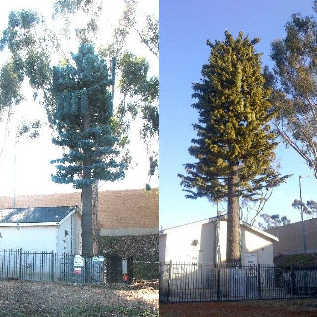
What are The Typical Costs Associated with Building A Camouflaged Monopole Tower
The costs associated with building a Camouflaged Monopole Tower can vary depending on several factors, including the tower's height, design complexity, camouflage materials used, location, site preparation requirements, and additional features such as antennas and equipment. Here are some typical cost considerations for constructing a camouflaged monopole tower:
1. Design and Engineering Costs:
Structural Design: Costs for designing the tower structure and ensuring it meets structural integrity and safety standards.
Camouflage Design: Expenses related to designing and implementing the camouflage pattern to blend the tower with its surroundings.
2. Tower Construction Costs:
Materials: Costs for the monopole structure, camouflage materials, foundation materials, and any additional components such as antennas and equipment mounts.
Labor: Expenses for construction labor, including site preparation, tower assembly, installation of antennas and equipment, and camouflage application.
3. Site Preparation Costs:
Land Acquisition: If land needs to be acquired for tower placement, associated costs will be incurred.
Permitting and Regulatory Compliance: Fees for obtaining permits, conducting environmental assessments, and complying with local regulations.
4. Equipment Installation Costs:
Antennas and Equipment: Costs for purchasing and installing antennas, transmitters, receivers, and other telecommunication equipment on the tower.
5. Maintenance and Operational Costs:
Routine Maintenance: Budget for ongoing maintenance, inspections, and repairs to ensure the tower remains structurally sound and visually effective.
Utilities: Costs for connecting the tower to power sources and telecommunication networks.
6. Miscellaneous Costs:
Transportation: Expenses for transporting materials and equipment to the construction site.
Safety Measures: Costs for implementing safety measures during construction and maintenance activities.
Factors Influencing Costs:
Height of the Tower: Taller towers typically require more materials and labor, leading to higher construction costs.
Location: Construction costs can vary based on the accessibility of the site, local labor rates, and regulatory requirements.
Design Complexity: Elaborate camouflage designs or special architectural features may increase construction costs.
Quality of Materials: Higher-quality materials and finishes may contribute to increased costs but can enhance the tower's longevity and aesthetics.
Overall, the total cost of building a camouflaged monopole tower can range from tens of thousands to hundreds of thousands of dollars or more, depending on the specific requirements of the project. It is essential to conduct a thorough cost analysis and consider all relevant factors to budget effectively for the construction of a camouflaged monopole tower.
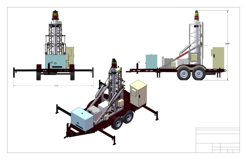
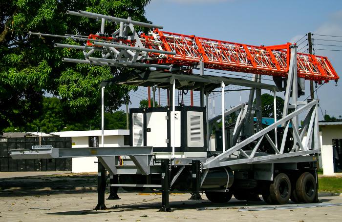
How Much Does A 5G Cell on Wheels ( COW) Cost
The cost of a 5G Cell on Wheels (COW) can vary significantly based on several factors, including the specific equipment and technology used, the capacity and coverage requirements, the duration of deployment, and whether it is a purchase or rental. Here are some cost considerations for a 5G Cell on Wheels:
Factors Influencing Cost:
1. Equipment Costs:
- Antennas and Radios: The cost of 5G antennas, radios, and other radio access network (RAN) equipment required for 5G connectivity.
- Networking Equipment: Costs for routers, switches, and other networking devices to establish connectivity.
- Power Systems: Batteries, generators, or alternative power sources to ensure continuous operation.
- Backhaul Connectivity: Expenses related to connecting the COW to the core network through fiber or wireless backhaul.
2. Construction and Installation:
- Tower and Mounting: Costs for the tower structure, mounting hardware, and installation.
- Site Preparation: Expenses for site survey, permits, and any necessary groundwork.
3. Technology and Capacity:
- 5G Capabilities: Costs associated with implementing 5G technology, such as massive MIMO antennas or beamforming equipment.
- Capacity: Higher capacity and coverage requirements may increase equipment costs.
4. Operational Expenses:
- Maintenance: Ongoing maintenance costs for the COW, including equipment upkeep and monitoring.
- Staffing: Costs for personnel to operate and maintain the COW during deployment.
- Security: Expenses for ensuring the security of the COW and its equipment.
5. Duration of Deployment:
- Rental vs. Purchase: Rental costs for short-term deployments may be lower than the upfront purchase cost of a COW.
- Long-Term Deployment: For extended periods, ongoing operational costs will need to be considered.
6. Additional Features:
- Remote Monitoring: Costs for implementing remote monitoring and management capabilities.
- Customization: Expenses for customizing the COW to meet specific requirements or branding needs.
Estimated Costs:
- Purchase Cost: A new 5G Cell on Wheels can range from tens of thousands to hundreds of thousands of dollars, depending on the specifications and capabilities.
- Rental Cost: Rental fees for a 5G COW can vary based on the provider, duration of deployment, and included services. Daily rental rates can range from a few hundred to several thousand dollars, or more.
Given the wide range of cost factors involved, it's essential to consult with telecommunications equipment providers, network operators, or rental companies for detailed quotes based on your specific requirements for a 5G Cell on Wheels deployment.
Why is lamination used in the core of a transformer?
Transformers are electrical devices that transfer electrical energy between two or more circuits through electromagnetic induction. Transformers consist of two main components: a primary winding and a secondary winding, both wound around a core.
The transformer core of a transformer plays a crucial role in its efficient operation. It is typically made using laminations or stacked layers of a magnetic material, such as silicon steel. But why is lamination used in the core of a transformer? Let's delve deeper into this question.
The primary reason for using laminations in the transformer core is to minimize energy losses. When an alternating current (AC) flows through a transformer, the magnetic field generated by the current causes the core to undergo rapid magnetization and demagnetization cycles. These cycles lead to two types of energy losses in the transformer core: hysteresis loss and eddy current loss.
Hysteresis loss occurs due to the repeated flipping of magnetic domains within the core material, resulting in energy dissipation in the form of heat. Laminating the core helps to reduce this loss by segmenting the core into thin layers. These layers disrupt the continuous path for magnetic flux, reducing the area enclosed by the hysteresis loop and thus minimizing hysteresis loss.
Eddy current loss, on the other hand, is caused by the circulating currents induced within the core material due to the varying magnetic field. By using laminations, the transformer core is effectively divided into isolated pieces, reducing the continuous loops that the eddy currents can flow through. This segmentation significantly decreases the cross-sectional area available for eddy currents and, consequently, reduces eddy current losses.
Moreover, laminations also enhance the mechanical strength and stability of the transformer core. By stacking and tightly clamping the laminations together, the core becomes more rigid and less susceptible to mechanical stresses and vibrations. This ensures that the core maintains its integrity and optimal magnetic properties throughout the transformer's operation.
In summary, the use of laminations in the core of a transformer is essential for minimizing energy losses, particularly hysteresis and eddy current losses. By dividing the core into thin layers, laminations reduce the path for magnetic flux and circulating currents, resulting in improved efficiency and overall performance of the transformer. Additionally, laminations enhance the mechanical stability of the core. These factors collectively contribute to the reliable and efficient operation of transformers in applications.
Unveiling the Magnetic Marvel The Fascinating World of Orientation Silicon Steel
In the realm of materials science, there exists a star that shines brightly in the field of electrical engineering – orientation silicon steel, or simply, oriented silicon steel. This isn't just any ordinary metal; it's a technological wonder that revolutionizes the way we think about electricity and magnetism.
Imagine a material so refined and engineered that it exhibits exceptional magnetic properties, making it the go-to choice for transformers and other electrical devices. Oriented electrical steel undergoes a complex manufacturing process involving rolling and annealing to align its magnetic domains in a specific direction. This alignment is crucial, as it significantly reduces energy loss during the transformation of electrical energy, enhancing efficiency by leaps and bounds.
But why should we care? Well, in today's world where sustainability and energy efficiency are paramount, every little bit of energy saved counts. Transformers equipped with orientation silicon steel play a pivotal role in reducing electricity wastage, thereby contributing to greener, more eco-friendly power grids.
Moreover, the material's thin gauge and high permeability allow for more compact transformer designs, making it an invaluable asset in the ever-shrinking world of electronics. From large-scale power stations to the tiny transformers inside our gadgets, orientation silicon steel is there, silently working its magic.
So, the next time you marvel at the seamless flow of electricity that powers your life, remember the unsung hero behind the scenes – orientation silicon steel. It's a material that's not just about steel; it's about innovation, efficiency, and a brighter, more sustainable future.
Which rivet is used for riveting magnesium alloy structures?
When riveting magnesium alloy structures, it is common to use rivets made of the same or compatible material. Magnesium rivets are specifically designed for joining magnesium alloys and offer good corrosion resistance and mechanical properties.
Types of Structural Rivets
Huck Structural Rivets
Multi Grip Blind Rivets
Uni Grip Blind Rivets
Hem Lock Blind Rivets
Advantages of Using Structural Rivets
High Shear and Tensile Strength
Vibration Resistance
Corrosion Resistance
Applications of Structural Rivets
-
Automotive and Aerospace Industries: These industries require fasteners that can withstand high-stress conditions. Structural rivets are often used in car frames, airplane fuselages, and other critical assemblies
-
Construction and Heavy Equipment: In construction, structural rivets are ideal for joining steel beams, heavy equipment, and other load-bearing components. Their high tensile strength ensures that these connections remain secure under heavy loads
-
Renewable Energy and Telecommunications: Structural rivets are used in the assembly of wind turbines, solar panel frames, and telecommunications towers due to their durability and ability to resist corrosion and weathering
Huck Bolts vs. Structural Rivets
What’s the Difference?
How to Choose the Right Structural Rivet
-
Material Compatibility: Ensure the rivet material matches the materials being joined. For example, aluminum rivets should be used with aluminum parts to avoid galvanic corrosion
-
Rivet Size and Grip Range: Choose a rivet with a grip range that accommodates the thickness of the materials being joined
-
Environmental Considerations: For applications exposed to moisture or corrosive environments, select rivets made from corrosion-resistant materials such as stainless steel
Installation and Tools for Structural Rivets
-
Air-Powered Guns: Ideal for frequent installations, offering fast and consistent results
-
Cordless Rivet Guns: Provide mobility and convenience but may need recharging during extended use
-
Manual Rivet Guns: Best for occasional installations and smaller projects
Conclusion and FAQs
Why Are Structural Rivets Better Than Traditional Fasteners?
What Are the Common Mistakes in Rivet Installation?
Are Structural Rivets Reusable?
How to Know if a Rivet Is Installed Correctly?
What’s the Expected Lifespan of a Structural Rivet?
Application of Terminal Blocks in Control Signal Transmission
Terminal blocks have wide applications in the field of control signal transmission. Control signal transmission refers to the transfer of signals from a controller to an actuator or other control devices to control devices, systems, or processes. Terminal blocks play a crucial role in connecting and transmitting signals in control signal transmission. Here are some applications of terminal blocks in the field of control signal transmission:
Automation equipment: pcb terminal block 2.54 mm are commonly used to connect sensors, actuators, and controllers in automation equipment. They provide reliable electrical connections to transmit control signals from the controller to the actuator, such as motors, valves, drivers, etc., to achieve control and monitoring of automated processes.
PLC (Programmable Logic Controller) system: PLC systems are widely used in the industrial automation field, and terminal blocks are used to transmit control signals from the PLC to various input and output devices. These input and output devices can be sensors, actuators, motors, switches, relays, etc., and terminal blocks provide reliable electrical connections and signal transmission.
Process control system: In industrial process control systems, terminal block 3 position are used to connect the controller and control devices, such as variable frequency drives, control valves, sensors, etc. They transmit control signals to monitor and control the process, adjust parameters, and ensure the stable operation of the process.
Mechanical control system: pcb terminal block plug connect the controller and various actuators, such as cylinders, motors, sensors, in mechanical control systems. They transmit control signals to control the movement and operation of mechanical equipment.
Thank you for considering the application of terminal blocks in control signal transmission. If you have any further questions or would like to discuss how our terminal blocks can benefit your specific application, please feel free to contact us.We are professional pcb terminal block manufacturers and terminal block factory.
Application of Terminal Blocks In Mechanical Control Systems
Terminal blocks are widely used for connecting and transmitting signals to control and operate mechanical equipment. Here are some specific applications of 5.08 pitch connector in mechanical control systems:
Motor control: 5.08 terminal block are used to connect motors and controllers to transmit motor control signals in electrical control circuits. By connecting the motor to the terminal 5.08, functions such as starting and stopping, forward and reverse rotation, and speed control can be achieved.
Sensor connection: Mechanical control systems often use various sensors, such as pressure sensors, temperature sensors, and photoelectric sensors, to detect and monitor the status of mechanical equipment. pcb connector terminal block are used to connect these sensors and transmit sensor signals to the controller for processing and decision making.
Switch control: Switches in mechanical equipment are used to control the starting, stopping, or switching of certain functions. Green screw terminal are used to connect control switches and controllers to transmit switch status signals, triggering corresponding operations or controls based on the switch status.
Position sensor connection: Mechanical control systems often use position sensors, such as encoders or position limit switches, to detect and provide feedback on the position information of the equipment. Pcb screw terminal connector are used to connect position sensors and controllers to transmit position signals to the control system, enabling accurate position detection and control.
Controller connection: Mechanical control systems typically use controllers (such as PLCs) to control and coordinate the entire system. Terminal blocks are used to connect the controller to the input and output interfaces of the equipment, transmitting control signals to various components effectively.
If you are interested in exploring how terminal blocks can enhance the performance and efficiency of your mechanical control systems, please feel free to contact us for further information.

