Different production processes of sintered and bonded neodymium magnets

     Ndfeb magnets can be divided into bonded NdFeb and sintered NdFeb. The difference between the two magnets is mainly in the production process: bonded neodymium magnet is injection molding by adding NdFeb magnetic powder to the adhesive; sintered neodymium magnet is vacuumed and molded by high temperature heating.


     1. Custom sintered neodymium magnet


custom sintered neodymium magnet


     In the process of sintering magnet manufacturing, neodymium magnet powder is mixed with appropriate additives and heated by high temperature sintering process. In the sintering process, the neodymium magnet powder particles will be combined to form a stable magnetic structure, thus forming a magnet with strong magnetism. Generally, through sintering, only blank can be produced, and then through mechanical processing (such as wire cutting, slicing, grinding, etc.) to become a magnet of various shapes. Sintered NdFeb is a hard and brittle material that is difficult to process, with large loss during processing. But the advantage is that sintered magnets usually have a high magnetic force and magnetic energy product, and have good temperature stability.


     Sintered Ndfeb is generally divided into axial magnetization and radial magnetization, and the magnetization direction can be customized according to the required work needs, while sintered Ndfeb has poor corrosion resistance and is easy to oxidize, so it is necessary to deposit on its surface, common nickel plating, galvanized, epoxy plating and so on.


     2. Custom bonded neodymium magnet


custom bonded neodymium magnet


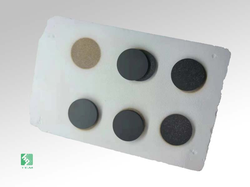
     The bonded neodymium magnet is used adhesive to bond the neodymium magnet powder with other metal elements, so it is magnetic in all directions and resistant to corrosion. In the manufacturing process, neodymium magnet powder and adhesive are mixed to form a magnet by pressure or injection molding. Because it is molded by injection molding, the density is generally only 80% of the theoretical, and the magnetism is weaker than the sintered neodymium magnet. But the manufacturing method of bonded neodymium magnets allows for more complex shapes and structures, and can be used in combination with other materials.


     The above is the introduction of the difference between the production processing technology of bonded NdFeb and sintered NdFeb. Both types of custom neodynium permanent magnets have their advantages and application scenarios. Sintered magnet is commonly used in applications that require high magnetic force and temperature stability, such as engines, sensors, and nuclear magnetic resonance equipment. Bonded magnet is suitable for applications that require custom shapes and structures, such as magnetic pusher pins, magnetic labels, etc.


cuatomized different shapu ndfeb magnets


     In short, the manufacturing process of sintered magnet and bonding magnet is different, and the choice of the appropriate process depends on the specific application needs.

What Are Globe Valves Used For

Nowadays, most industries are using high-tech and modern types of valves to enhance production and operation.

Out of all the other types of industrial valves, globe valves are widely used in the oil, gas and fuel industries.

There are many uses of this type of valve as it works to stop as well as regulate the flow of liquids. If you want to know more about globe valves and their uses, follow this article.

What Are Globe Valves?

It is a type of linear motion valve which is used in different types of industries. It is designed in a way that you can use it for throttling as well. 

It has a spherical shape like a globe and comes with a disc. The disc moves in order to block as well as allow the flow of substances. When you close the valve, the disc entirely covers the pathway to stop the flow of fluids.

However, when you open the valve, the disc moves upwards in order to clear the pathway and allows substances to flow freely. It is mostly used for isolation and throttling purposes.

This type of industrial valves has good shutoff capability. You can use it to prevent leakages. Apart from that, it also offers good throttling capacity.

The stroke is shorter, which makes it easy to use and maintain. It is available in different types and designs. 

Applications and Uses of Globe Valves:

Globe valves have many applications. It is used for industrial as well as domestic purposes. The majority of the industries with plumbing needs use this type of valve. Here are some applications and uses of globe valves. 

Cooling Water Systems:

A globe valve helps maintain the heat and cooling of the system by regulating the flow. It helps in the adjustment of the temperature of the system in relation to the demand of heat or cool by taking the measurement of the changes in pressure. As a result, a valve regulates the amount of heat produced by the boiler. 

Fuel Oil Systems: 

A Globe Valve is a very important component of fuel oil systems. It helps to prevent and control the rate at which gasoline is burnt in an engine, thus enabling the engine to maintain a constant pressure of fuel at all times. It is usually found on the side of the engine near the firewall. It has a round-shaped body and has two cones on its side. 

Chemical Feed Systems:

A Globe valve is one of the important parts of chemical feed systems. It helps in the complete process of converting the feed mixture into a liquid, and it also helps in the separation of solids from the liquid mixture. A Globe valve has a piston, and it is rotatable. In this, the piston moves up and down due to the increase and decrease in pressure. 

Boiler, Main Stem Vents and Drains:

The globe valve is used in main steam and boiler rooms and drains as well. They can be used for controlling the amount of steam that enters a room from outside, regulate the water temperature in the boiler or condensate drain, or act as a thermostatic valve. It is commonly used in the hot water tank to prevent the loss of hot water from the tank through the pipes.

Turbine Lube Oil System:

A globe valve is used in a turbine lube oil system as it allows the flow of turbine oil to be limited to a single point. The oil is pumped by means of a turbine into a sump tank that is located above the turbine.

Product Inspection of Stainless Steel Reducers

Inspection of Stainless Steel Reducers
1. Geometry analyses of stainless steel reducers
The distribution trends of wall thickness of big and small concentric reducers are exactly the same. From the large end face to the section close to the small end face, the wall thickness changes from thin thickness to thick one. The inner hole of the small end has been turned after forming, and part of the wall thickness has been removed. However, the wall thickness of end faces of small ends is thinner than that of end faces of large ends, which is exactly the opposite of the eccentric reducer. This is caused by the manufacturing process. When the wall thickness of the axial section changes, there is obvious regularity for changes between the warp threads, but there is also a certain degree of dispersion.

2. Analyses of strength
The distribution trends of surface hardness of the large and small eccentric reducers are roughly the same, but they are not completely the same. The main difference is the hardness of the small end. The hardness of the small end of small eccentric reducers is higher, while the hardness of that of large eccentric reducers is lower. The tensile strength of the sample is 6.1% and 11% higher than the estimated strength value of the empirical formula. The yield strength and tensile strength of the sample 1 were increased by 9.0% and 2.0% respectively before production, and those of the sample 2 were increased by 26.4% and 8.8% compared with before production).

3. Conclusion
(1) The geometric dimensions of large and small ends of stainless steel reducers are more accurate, but the wall thickness is very uneven. As for stainless steel reducers with straight sections, the wall thickness of the small end of the eccentric reducer is thicker than that of the large end, while the wall thickness of the small end of the concentric reducer is thinner than that of the large end. The wall thickness of the reducing elbow is more uniform. Therefore, the geometric dimensions of the large and small ends must be measured when they are tested.
(2) The wall thicknesses of the stainless steel reducers tested are all extremely thick. It is recommended that a comprehensive wall thickness inspection record should be performed before they are used. With a basis for online thickness measurement to determine the thinning, the corrosion rate can be accurately reflected so as to ensure the safe operation of the pipeline.
(3) The ellipticity of the stainless steel reducer is less than 2%; the bending radius error of the reducing elbow is also small and can be ignored.
(4) The surface hardness of the two ends of the stainless steel reducer is about 35% lower than that of the middle section on average.
(5) After the final normalizing treatment, the yield strength and tensile strength of the stainless steel reducer made of large-diameter pipes by hot pressing are significantly improved.

Alloy Steel Pipes

Materials of alloy steel pipes 
Alloy steel pipes have good hardness, which are widely used for pipelines for transporting oil, natural gas, gas, water and certain solid materials. The common alloys are ferroalloys, ferro-chromium alloys, iron-nickel alloys, aluminum alloys(light weights) and copper alloys(good thermal conductivity). The main materials include 16-50Mn, 27SiMn, 20-40Cr, 12-42CrMo, 16Mn, 12Cr1MoV, T91, 27SiMn, 30CrMo, 15CrMo, 20G, Cr9Mo, 10CrMo910, etc. Alloy steel pipes made from 16Mn belong to low alloy steel pipes.
 
Applications of alloy steel pipes
Alloy steel pipes are mainly used for high-pressure and high temperature pipelines and equipment such as power plants, nuclear power, high-pressure boilers, high temperature superheaters and reheaters.
 
Three expressions of alloy steel pipe specifications
1. The first one is the outer diameter plus wall thickness. For example, an alloy steel pipe with an outer diameter of 57mm can be indicated by 57x3.
2. The second one is using the inner diameter, that is, the nominal inner diameter. For example, an alloy steel pipe with an outer diameter of 57mm is indicated by DN50.
3. The third one is the inch. For example, an alloy steel pipe with an outer diameter of 57mm can be indicated by 2 inches (1 inch equals to 25.4mm.)
 
Specific welding steps of alloy steel pipes
Welding processes of alloy steel pipes are heating before welding, quenching and tempering after welding.
 
Heating
Before welding the alloy steel pipe, it should be heated, and weld it after the temperature is controlled for 30 minutes. The heating and virtual beam temperature tempering of welding are actively operated by the temperature control cabinet for temperature adjustment. Adopt far infrared tracking heat treatment furnace plates. Intelligently and actively set the graph and record the graph, and use the thermal resistance to accurately measure the temperature. The thermal resistance measuring point is from 15mm to 20mm away from the edge of the weld during heating.
 
Welding methods
1. In order to prevent welding deformation of the alloy steel pipe, each column joint is welded symmetrically by two people, and the welding direction is from the middle to the two sides. After welding one to three layers, reverse planing should be carried out. After the carbon arc gouging is used, the welding equipment needs to be polished. The welding surface should be nitridation treated to show the metal texture and prevent the surface carbonization from causing cracks. The outer hole is welded once, and the remaining inner holes are welded once.
2. When welding alloy steel pipes with two layers, the welding direction should be opposite to that of the layer of alloy steel pipes. The butt welds of each layer are separated by 15 to 20mm.
3. The welding current, welding speed and number of overlapping layers of multiple welding machines should be maintained.
4. In welding, you must start welding from the pilot arc board and finish welding on the pilot arc board. Cut, polish and clean after welding.
 
Quenching and tempering after welding
After the seam are welded, it should be tempered within 12 hours. If the alloy steel pipe cannot be quenched and tempered immediately, heat preservation and slow cooling should be adopted. When the alloy steel pipe is tempered, temperatures of the two thermal resistances should be measured and the thermal resistance should be welded on both sides of the seam.

Technical requirements for steel pipes

This technical specification is suitable for the bidding for the procurement of steel pipe projects.

Executive standards

The steel pipe shall meet the following standards:

Quality standard like Spiral Welded Submerged Arc Welded Steel Pipes for Urban Heating CJ/T3022-1993 or Technical Delivery Conditions of Oil and Gas Industry Transportation Steel Pipes GB/T9711.1-2017 should be implemented for spiral welded pipes.

Seamless Steel Pipe for Fluid Transportation GB/T8163-2008 should be carried out as quality standards for seamless steel pipes.

Technical requirements for steel pipes

Materials

The steel pipe should be made of spiral seam welded steel pipes with Q235B.  The seamless steel pipe should adopt 20# steel.

Technical specifications

The quality and size of spiral seam welded steel pipes should conform to IS09330-1 or GB9711.1~2017 standards.

Spiral seam welded steel pipes should ensure that the minimum yield strength is greater than 235N/mm2.

Weld joints of steel pipes must meet the technical requirements of DIN1626 or GB3323-87.

Specifications, weights and errors of steel pipes

The supply of steel pipes shall comply with the relevant regulations in the latest GB9711.1-2017 or GB8163-2008.

The normal supply length of the steel pipe should be 12m with a length deviation of 0/+25mm.  When the length of the steel pipe is less than 12m due to the valve, compensator or pipeline turning, it should be supplied according to the actual length on site.

The thickness deviation requirements of the raw material steel plate of the steel pipe: when DN is 800mm, the negative thickness deviation should be smaller than or equal to 0mm.  When DN is greater than 800 and smaller than or equal to 1100mm, the thickness negative deviation should be less than or equal to 0mm.  When DN is greater than 1100 and smaller than or equal to 1200mm, the thickness negative deviation should be less than or equal to 3%.

The end of the steel pipe should be grooved.  The groove angle should be 30° and the deviation 0°/5°.  The size of the blunt edge should be 1.6±0.8mm.

The end surface of the steel pipe shall be perpendicular to the axis of the steel pipe.  When the nominal outer diameter is less than 508mm, the limit deviation shall not be greater than 1.5mm.  When the nominal outer diameter is greater than or equal to 508, the limit deviation shall not be greater than 2.0mm.

The ovality of the steel pipe end within 100mm shall not exceed ±1%D.

Requirements for manufacturers

In order to ensure the quality of the project, the following requirements are put forward for the materials and manufacturers of steel pipes and fittings:

The steel quality standards of steel pipes are equal to or higher than those of famous steel pipe manufacturers in China.

The quality standard of the steel pipe is equal to or higher than the product standard produced by the bidder, and the selected manufacturer must be approved by the tenderer and indicate in the bidding document.

At the same time, photocopies of the delivery quality certificate of the steel pipe raw materials, the quality certificate of the steel pipe, the special equipment manufacturing license (pressure pipe) that the manufacturer should have, and the inspection report issued by the local quality inspection department must be attached to the bidding documents.

Large-Diameter Seamless Steel Pipe Related Details

Large-diameter seamless steel pipes can be divided into straight seam arc welded steel pipes and straight seam submerged arc welded steel pipes according to traditional processes. The production process of straight seam welded pipe is simple, low cost, rapid development, and high production efficiency.

First, the steps to explain the large-diameter seamless steel pipe
1. Large-diameter seamless steel pipes are made of a single piece of metal and have no seams on the surface. They are called seamless steel pipes. Seamless steel pipes have hollow sections and are suitable for transporting fluids such as oil, water, and some solid materials.
2. Large-diameter seamless steel pipes are widely used to manufacture structural parts and mechanical parts, such as oil drill pipes, automobile drive shafts, bicycle frames, steel scaffolding, etc. Straight seam steel pipe refers to a steel pipe in which the weld seam is parallel to the longitudinal direction of the steel pipe. When seamless pipes and straight-seam pipes have the same diameter and wall thickness, the pressure and robustness of seamless pipes are much greater than that of straight-seam pipes.
3. Large-diameter seamless steel pipes and welded steel pipes are steel pipes made by crimping steel plates or steel strips.

Second, a complete list of methods for large-diameter seamless steel pipes
1. Seamless steel pipes have much higher corrosion resistance, pressure resistance, and high-temperature resistance than welded steel pipes. When seamless pipes and straight-seam pipes have the same diameter and wall thickness, the pressure and robustness of seamless pipes are much greater than that of straight-seam pipes.
2. Large-diameter seamless steel pipe has a hollow section and is suitable for transporting fluids, such as oil, water, and some solid materials. The production process of straight seam welded pipe is simple, low cost, rapid development, and high production efficiency.
3. Seamless steel pipes have much higher corrosion resistance, pressure resistance, and high-temperature resistance than welded steel pipes. A welded steel pipe is a steel pipe made of steel plates or steel strips pressed together.

Introduction of carbon steel flanges

Carbon steel flange is a kind of common connecting pipe component, which is widely used in petroleum, chemical, natural gas and other industries. It is usually made of carbon steel, with high strength, corrosion resistance and high temperature characteristics, suitable for a variety of harsh working environment.

There are many types of carbon steel flanges, including blind plate, butt welding, thread, flange, etc. . Each type has a different way of connecting and usage scenarios to meet a variety of different needs. Butt-welding flange is the most common one, it can be fixed to the pipeline through welding to ensure the stability and sealing of the connection. Thread flange is suitable for low pressure environment, through the thread connection to achieve pipe connection. Blind flange used to block the flow of fluid in the pipeline, often used for pipeline closure or repair.

One of the advantages of carbon steel flanges is that the material strength is high, able to withstand high pressure and high temperature working conditions. It can be used in harsh environment for a long time, with a long life. The carbon steel flanges also have good corrosion resistance and are not easy to be corroded and oxidized when in contact with various media, thus ensuring the safety and reliability of pipelines.

Carbon steel flanges are relatively simple to install and maintain and can be quickly removed and replaced. Its structure design is reasonable, has the good sealing, can prevent the leakage and the outside impurity entering. At the same time, carbon steel flanges have lower cost and play an important role in the design and construction of pipeline system.

In a word, as an important part of connecting pipeline, carbon steel flange has the characteristics of high strength, corrosion resistance and high temperature resistance. The utility model has the advantages of reasonable structure design, simple installation, good sealing performance and lower cost, and is widely used in petroleum, chemical industry, natural gas industry and the like. Carbon steel flanges are a reliable and economical choice for both new construction and maintenance projects.

Manufacturing method of seamless steel pipe

Seamless steel pipe is a kind of long steel with hollow section and no joint around.  The seamless steel pipe has hollow section and can be used as the pipeline for conveying fluid, such as oil, natural gas, gas, water and some solid materials.  Compared with solid steel such as round steel, seamless steel pipe is lighter in weight when its bending and torsion strength is the same.  It is a kind of economic section steel, which is widely used in the manufacture of structural parts and mechanical parts, such as oil drill pipe, automobile transmission shaft, bicycle frame and steel scaffold used in construction.  Using seamless steel pipe to make annular parts can improve the material utilization rate, simplify the manufacturing process, save materials and working hours, such as rolling bearing rings, Jack sleeves and so on.  Steel pipe is also an indispensable material for all kinds of conventional weapons.  Gun barrel and barrel should be made of steel pipe.


According to different production methods, it can be divided into hot-rolled pipe, cold-rolled pipe, cold drawn pipe, extruded pipe, etc.

1.Hot rolled seamless steel pipe is usually produced on the automatic pipe mill.  After checking and removing the surface defects of the solid tube blank, it is cut into the required length, centring on the end face of the piercing end of the tube blank, and then sent to the heating furnace for heating and piercing on the piercing machine.  In the process of piercing, a cavity is gradually formed inside the tube blank under the action of the roller and the plug, which is called the blank tube.  Then it is sent to the automatic pipe rolling mill to continue rolling.  Finally, the wall thickness is adjusted by the whole machine, and the diameter is calibrated by the sizing machine to meet the specification requirements.  It is an advanced method to produce hot rolled seamless steel tube by continuous pipe mill.

2.  In order to obtain smaller size and better quality seamless tubes, cold rolling, cold drawing or a combination of both must be used.  Cold rolling is usually carried out on a two high mill.  The steel tube is rolled in an annular pass composed of a variable cross-section circular groove and a stationary conical plug.  Cold drawing is usually carried out on 0.5-100t single chain or double chain cold drawing machines.


3.  In extrusion process, the heated tube blank is placed in a closed extrusion cylinder, and the piercing rod and the extrusion rod move together to extrude the extruded part from the smaller die hole.  This method can produce small diameter steel pipe.

Rust removal method of steel pipe

It mainly uses steel wire brush and other tools to polish the steel surface, which can remove loose or raised oxide skin, rust, welding slag, etc.

Generally, chemical and electrolytic methods are used for pickling treatment. Chemical pickling is only used for pipeline corrosion protection, which can remove oxide skin, rust and old coating. Sometimes it can be used as the reprocessing after sand blasting. Although chemical cleaning can make the surface reach a certain degree of cleanliness and roughness, its anchor pattern is shallow and easy to pollute the environment.

Spray (throwing) rust removal is a high-speed rotation of spray (throwing) blades driven by a high-power motor, so that steel sand, steel shot, wire section, minerals and other abrasives can spray (throwing) on the ASTM A106 A53 Gr. B Carbon Steel Seamless Fluid Pipe surface under the centrifugal force, which can not only completely remove rust, oxides and dirt, but also achieve the required uniform roughness under the action of strong impact and friction of abrasives. After spraying (throwing) and removing rust, not only the physical adsorption on the pipe surface can be expanded, but also the mechanical adhesion between the anticorrosive coating and the pipe surface can be enhanced. Therefore, spraying (throwing) is an ideal way to remove rust. Generally speaking, shot blasting (sand) is mainly used for inner surface treatment of pipes, while shot blasting (sand) is mainly used for outer surface treatment of pipes.

Why use cores in transformers?

Transformers often require/use iron cores because they operate on magnetic forces, which are difficult to understand when sharing certain characteristics with good old "electricity" (ohms, volts, amperes, etc.). Let's try some simplified ways to get the overall idea.

Start with a screwdriver - just a cylindrical coil. If we let the current flow through, a magnetic field (we call it the H field) is formed. The field depicted with the imagined field line flows up through the center of the coil, then disperses again after leaving the cylinder, then reassesses and re-enters the other end. You've seen the picture in the textbook. The magnetic field is strong and contained inside the cylinder (ID), while the magnetic field strength is weak outside (OD) because it diffuses in space. If the H magnetic field interacts with "anything" around the coil, whether it is vacuum, air or iron, it produces what we call a B magnetic induction field within the "material", the strength of which depends on the strength of the magnetic field. The properties of "matter" are called "permeability". For a given magnetic field strength H, vacuum or air forms a relatively weak induction field B, while iron forms a very strong sensing field (1000 times stronger).

If we make a second coil (solenoid valve) and parallel it to the first coil in the air, a portion of the weak air sensing field B flows through the center of the second coil. If we change the current in the first coil, its B field will change slightly, as will the B field flowing through the second coil (absolutely by a small margin). This is not only because the entire B magnetic field is weak, but also because only a portion of the entire B magnetic field actually passes through the second coil. Recall maxwell's equation, saying that the voltage sensed in the coil depends on the magnitude of the change through its B field. Therefore, in our case, since the B-field change through the second magnetic field is very small, we can expect only one weak voltage to be sensed in the second coil.

To make it better, we can place a piece of iron in the center of the first coil. This will make the B field in the iron stronger than the B field in the air. In addition, we can extend the iron sheet into a ring so that it passes through the second coil. (We've made a transformer core ). Most of the enhanced B magnetic field from the first coil now passes through the iron into the second coil, and the magnetic field change caused by the current change in the first coil is amplified, resulting in a greater inductive voltage in the second coil. Coil.

That's why we use iron core simplification in many, but not all, transformers.