Roofing Tincaps Enhancing Roof Construction and Long-Term Performance

As a homeowner or a contractor embarking on a roofing project, it's crucial to pay attention to every detail that contributes to its durability and longevity. One such key component often overlooked is the roofing tincap. In this article, we will delve into the significance of roofing tincaps, their benefits in securing roofing nails, and how they play a pivotal role in maintaining the long-term performance of your roof.


1. What are Roofing Tincaps?

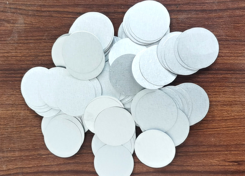
Roofing tincaps are small metal discs designed to be used in conjunction with roofing nails. Made from durable materials such as galvanized steel or aluminum, these tincaps are placed over the nail head and act as a protective barrier, preventing water penetration and ensuring a tight seal. Their design also aids in distributing pressure evenly, minimizing the risk of nail pops and roof leaks.


1-5/8 inch Roofing TinCaps


2. Benefits of Roofing Tincaps:

a. Enhanced Waterproofing: By effectively sealing the nail penetrations, roofing tincaps provide an additional layer of waterproofing to your roof. This helps to prevent water leakage, rot, and other potential damages caused by moisture infiltration.

b. Increased Wind Resistance: The secure installation of roofing tincaps helps to reinforce the overall integrity of the roofing system. They prevent shingles from lifting and can withstand high wind speeds, reducing the risk of wind-driven damage during storms or hurricanes.

c. Longevity and Durability: Roofing tincaps, especially those made from galvanized steel or aluminum, are highly resistant to corrosion, rust, and weathering. Their robust construction ensures that they will endure harsh environmental conditions, contributing to the longevity and durability of your roof.


3. Role in Long-Term Roof Performance:

Roofing tincaps play a vital role in maintaining the long-term performance of your roof. They help to preserve the structural integrity by securing the roofing nails, preventing them from loosening or being driven in too far. This, in turn, prevents shingle uplift, reduces the risk of leaks and subsequent damage, and ensures a stable and watertight roof for years to come.


4. SUNWELL Roofing Tincaps

When it comes to roofing tincaps, SUNWELL is a trusted name known for its superior quality and reliable products. SUNWELL roofing tincaps offer an array of advantages that make them the go-to choice in the industry. In addition to the benefits mentioned earlier, SUNWELL roofing tincaps are designed with precision and backed by cutting-edge technology, ensuring a perfect fit and effortless installation.


Furthermore, SUNWELL's exceptional customer service sets them apart from others. Their team of experts is dedicated to providing personalized assistance, answering queries, and guiding you through the process, guaranteeing a seamless experience from start to finish.


In conclusion, roofing tincaps are an essential component of any roof construction project. By using roofing tincaps, you can enhance the waterproofing, increase wind resistance, and extend the longevity of your roof. And when it comes to roofing tincaps, SUNWELL roofing tincaps are your ultimate solution, offering exceptional quality, advanced technology, and unparalleled customer service. Invest in roofing tincaps and enjoy the benefits of a secure and long-lasting roof for years to come.
Does A Ball Valve Need to be Fully Open?

A ball valve does not always need to be fully open, but whether it should be fully open or not depends on the application and the design of the valve.

1. Designed for On/Off Control

Ball valves are typically designed for full on/off control, meaning they function best when they are either fully open or fully closed. This is because they allow for minimal resistance to flow when fully open and provide a complete seal when fully closed. Operating a ball valve in a partially open position for extended periods can lead to issues like:

(1) Turbulent Flow: Partial opening can create turbulence, increasing wear on the valve and pipe.

(2) Damage to the Ball and Seals: The high velocity and turbulence near the partially open ball can cause damage to the sealing surfaces.

(3) Vibration and Noise: A partially open ball valve may cause vibration or noise due to the irregular flow.


2. Throttling Applications

Although ball valves are primarily used for on/off applications, they can be used for throttling (controlling flow) in certain cases. However, for precise flow control, globe valves or other throttling valves are more suitable because they are designed to handle partial openings without causing damage to the valve or creating inefficiencies in flow control.


3. Special Ball Valves for Throttling

Some ball valves are specifically designed with V-port balls or multi-port designs, which allow for better flow control when partially open. These valves provide more precise control over the flow compared to standard ball valves and can be safely used in a partially open position.


While a ball valve can operate in a partially open position, it is generally recommended to use it fully open or fully closed for optimal performance and longevity, unless it is a specialized ball valve designed for throttling. For precise flow regulation, other types of valves may be more appropriate.

Is a ball valve a shut-off valve?

As a valve widely used in fluid control systems, the ball valve is typically regarded as an efficient shut-off valve. Its unique structural design allows it to fully open or close the pipeline with just a 90-degree rotation, achieving rapid shut-off or opening of the media flow. Therefore, ball valves are widely used as shut-off valves in various industrial applications, especially in situations requiring frequent operation, quick response, and reliable sealing.


The Working Principle and Shut-off Function of Ball Valves

The core component of a ball valve is a ball with a through-hole. When the valve stem is operated, the ball rotates along the axis of the stem. When the through-hole in the ball aligns with the pipeline, fluid can flow freely; when the ball rotates 90 degrees, the through-hole becomes perpendicular to the pipeline, thereby stopping fluid flow. This simple yet effective working principle makes ball valves highly suitable as shut-off valves.


Compared to other types of valves, such as gate valves or globe valves, ball valves have a significant advantage in operating speed. They can achieve full opening or closing in a short time, and the opening and closing action requires only a 90-degree rotation of the valve stem. This feature makes ball valves excel in handling emergency situations.


Advantages of Ball Valves as Shut-off Valves

(1) Quick opening and closing:

The 90-degree rotation design of ball valves enables extremely fast operation, without the need for multiple turns to fully open or close like gate valves. This makes them particularly suitable for situations requiring emergency shut-off.

(2) Good sealing performance:

Ball valves typically use metal or elastic materials as sealing elements, providing a high degree of sealing performance. In the fully closed position, ball valves can effectively prevent media leakage, ensuring the safety and efficiency of the pipeline system.

(3) High durability:

Ball valves have a simple structure and smooth internal flow passage, resulting in low resistance as the medium flows through, which reduces valve wear. Additionally, ball valves maintain stable performance in high-pressure, high-temperature, and corrosive environments, offering a long service life and low maintenance costs.

(4) Wide applicability:

Ball valves are suitable for various media, including liquids, gases, steam, and some corrosive fluids. Whether in the oil and gas industry, chemical production, water treatment, or power generation, ball valves are one of the most commonly used shut-off valves.


The Application of Ball Valves in Industry

As shut-off valves, ball valves play an important role across various industries, especially in industrial applications with high fluid control requirements. The following are common application areas for ball valves:

(1) Oil and gas:

Ball valves are commonly used in oil and gas pipeline systems. Their reliable sealing performance and quick opening and closing capabilities ensure that, in emergency situations, the flow of media can be rapidly shut off, safeguarding the system's safety.

(2) Chemical industry:

In chemical plants, when handling corrosive media or toxic gases, the corrosion resistance and high sealing performance of ball valves are particularly important.

(3) Water treatment and supply systems:

In water treatment and municipal supply systems, ball valves are used to control the flow of water, facilitating maintenance operations and ensuring the normal operation of the pipeline system.

(4) Power industry:

In high-temperature and high-pressure environments, the durability and sealing performance of ball valves make them an ideal choice for power plants and steam systems.

Measures To Prevent Abnormal Boost of Cryogenic Valves

If the medium remained in the cavity after the cryogenic gate valve is closed, the residue will gradually absorb the heat in the air and re-gasify. After the gasification, it will expand violently up to 600 times and generate extremely high pressure on the valve, which is called 'abnormal boost'.


When the unusual occurrence happens, the wedge will be pressed firmly onto the seat and can’t be opened. The high pressure will push the gasket of the flange out or damage the packing. It may also deform the body and bonnet, significantly reducing its sealing performance. What’s worse is that the valve breaks down and causes economic loss.


In order to prevent the misfortune of abnormal pressure increase, we take following measures:


1. Set an orifice, also known as pressure-balancing orifice or exhaust orifice, that is, a small hole drilled on the inlet side of the flexible gate or double gate serves as a pressure-balancing hole in the inner cavity of the valve and the inlet side. When the pressure in the valve cavity increases, the gas can be discharged through the small hole. This method is relatively simple and has been widely adopted. Once an orifice is added to the valve, there should be an arrow dedicating the direction of the flow.


2. Set an outlet pipe on the valve or install a safety valve to discharge abnormal high pressure. Generally, a safety valve is installed on the cover. When the pressure rises to a certain value, the safety valve opens and balances the pressure to ensure the safety of the body.  Or an exhaust valve can also be installed in the lower part of the valve body to drain the residual medium in the cavity, preventing abnormal boost.


Related products: cryogenic ball valve, cryogenic floating ball valve


Physical Reason Why Check Valve Born

For high-pressure piping systems where multiple pumps are used together, the problem of water hammer in the piping system is even more acute.


Water hammer is a pressure wave of the ever-changing flow in a pressure pipe, which is a hydraulic shock caused by a pressure rise or fall due to the change in the fluid flow rate in the pressure pipe.


Water hammer is the combined result of the incompressibility of the fluid, the inertia of the fluid motion and the elasticity of the pipe.


In order to prevent the potential danger of water hammer in the pipelines, over the years, researchers use certain new structures, new materials in the design of the check valve. While ensuring the applicable performance of the check valve, the creative endeavor has made gratifying progress in reducing the impact force of the water hammer


Check valve is a valve that relies on the flow of the medium itself to automatically opens and closes the valve plate. It is used to prevent the back-flow of the medium, so it is also known as non-return valve, uni-direction valve.


Check valve is an automatic valve, its primary function is to prevent the media back-flow, prevent the pump and drive motor from reversing, as well as the leakage of container media.


Check valve can be divided into swing check valve and lift type check valve.

Structural Features of Floating Ball Valve

The ball of the floating ball valve is suspended. Under the pressure of the medium, the ball will move and press against the outlet side of the seal. The floating ball valve is only widely used for medium and low-pressure conditions because the pressure of the medium completely transfers the ball weight to the seal at the outlet. For the same reason, the design of the floating ball valve should focus on whether the material of the sealing ring can withstand the load of the ball and medium. Dvsvalve supply different types of floating ball valve, including bronze floating ball valve,forged steel ball valve and other customized valves.


Features:


1. Floating ball valve has the smallest flow resistance among all types of valves; when the full-bore ball valve is open, the ball channel, body channel and connection pipe are of the same diameter, so the media can flow without loss.


2. Quarter-turn to open and close the valve fully, quickly; Floating ball valve also has the advantage of being smaller, lighter and easier to install in piping than gate and globe valves with the same specifications.


3. Floating ball valves have locking devices in both fully open and fully closed positions to prevent misoperation of the valve and to ensure the correct position of the valve.


4. The float valve has an anti-blowout stem, which is installed from the bottom to prevent the stem from blowout out of pressure. The design also will form metal contact with the valve body to ensure the seal of the stem when it catches fire.


In short, the floating ball valve has a valve wedge that is a ball with a round hole. It can be rotated from 0 degrees to 90 degrees around axis of the stem, which is driven by the lever, for opening and closing functions.


Floating ball valve also has a compact construction that opens and closes quickly, which helps to regulate the flow of media in the pipe by rotating 90 degrees and finally closing the valve. It‘s  size of the path is of the same diameter as the pipe’s, but boats low flow resistance and high flowing capacity. The stem that mounted from the bottom ensures safe use of the valve.

Testing methods of various valves Ⅲ

6.For globe valve and choke valve

When it comes to the strength test of the globe valve and the choke valve, the assembled valve is usually placed in the pressure test frame. Then, open the wedge, inject the medium to the specified value, finally check if the body and the bonnet of the valve‘sweat’or leak.


Only the globe valve can be put in the sealing performance test. During the test, keep the stem vertical; open the wedge. Introduce the medium from the down end to the specified value; check the packing and gasket. If the valve is clear, close the wedge and check the other end.


If the valve strength and sealing test are both required. Do the strength test first. Then turn down the pressure to the specified value of the sealing test, check the packing and gasket; then close the wedge. Check the outlet end whether the sealing surface is leaking.


7.For gate valve

The strength test of the gate valve is the same as that of the globe valve. There are two methods for the gate valve sealing test.


Open the wedge, turn up the inner pressure to the specified value; Then close the wedge, immediately take out the gate valve, check whether there is leakage at the seals on both sides of the gate, or directly inject the test medium into the plug on the valve cover to the specified value, check the seals on both sides of the wedge. This method is called the 'intermediate pressure test'. This method should not be carried out to the gate valve less than DN32.


Another method is to open the gate and increase the test pressure to the specified value; then close the gate and open the blind disc(flange cover) at one end to check whether the sealing surface leaks. Then turn around the valve and repeat the above test until it is qualified.


The sealing test to the packing and gasket of the pneumatic gate valve should be conducted before the gate sealing test.


8.For safety valve

The strength test of the safety valve is the same as that of other valves.  When testing the lower part of the body, the pressure is introduced from the inlet end and the sealing surface is closed; when test the upper part of the body and the bonnet, the pressure is introduced from the outlet end and the other end is closed. The valve body and bonnet are qualified if no leakage happens in the given time.


More articles about testing methods of various valves:

Pressure testing methods of various valves Ⅰ

Pressure testing methods of various valves Ⅱ

Valve Technology Questions and Answers I

1. How do the pressures of ultra high pressure valves, high pressure valves, medium pressure valves, and low pressure valves differ?

Ultra high pressure valve, nominal pressure PN100MPa; high pressure valve, nominal pressure PN10.0MPa-80.0MPa; medium pressure valve, nominal pressure PN2.5MPa-PN6.4MPa; low pressure valve PN1.6MPa.

2. How to distinguish the calibers of extra large caliber valves, large caliber valves, medium caliber valves and small caliber valves?

Extra large valve, nominal size DN1400mm; Large diameter valve, nominal size DN350mm-1200mm; Medium diameter valve, nominal size DN50mm-300mm; Small diameter valve, nominal size DN40mm.

3. How are high-temperature valves, heat-resistant valves, low-temperature valves, and ultra-low-temperature valves distinguished?

High temperature valve, medium working temperature is greater than 450 ; heat-resistant valve, medium working temperature is above 600 ; low temperature valve, medium working temperature is -29 ~ -100 ; ultra low temperature valve, medium working temperature is less than -100 .

4. How is the opening and closing direction of the universal valve specified?

The opening and closing directions of the universal valve are specified as: clockwise to close and counterclockwise to open.

5. How is the minimum stem diameter and minimum stem diameter specified?

The minimum stem diameter refers to the diameter of the part of the stem that contacts the packing. The minimum stem diameter refers to the diameter of the stem thread undercut.

Valve Technology Questions and Answers II

  1. What is the value of flow coefficient Kv? What is the flow coefficient Cv?

    Volumetric flow of water flowing between 5 ° C (40 ° F) and 40 ° C (104 ° F) through the valve to produce a pressure loss of 1 bar (14.7 psi), expressed in cubic meters per hour.

    Kv = Cv / 1.156

    Flow coefficient Cv: It is the mass flow rate when water flows through the valve at 15.6 ° C (60 ° F) to produce 1psi, expressed in gallons per minute.
  2. What is a pressure bearing?

    Design parts that can withstand the pressure of pipeline media, such as valve body, bonnet, packing gland, valve stem, gasket and stud.
  3. What is a pressure control part?

    Refers to those parts used to prevent or allow the flow of media, such as valve seats, balls, discs, gates, discs and other seals.
  4. What is ferritic stainless steel? What is austenitic stainless steel? What is the difference between the applicable media?

    The solid-solution solid-centered cubic lattice of carbon in α-iron in stainless steel is ferritic stainless steel; the solid solution of carbon in γ-iron forms face-centered cubic lattice is austenitic stainless steel.

    Ferritic stainless steel is suitable for corrosive media such as acetic acid and lactic acid; austenitic stainless steel is suitable for corrosive media such as nitric acid, sulfuric acid and acetic acid.

Valve Technology Questions and Answers III

  1. What is the difference between Cast iron and Cast steel?

    The difference between Cast iron and Cast steel is their carbon content. Cast Iron with carbon content greater than 2.06% is iron; steel with carbon content between 0.02% and 2.06% is steel.
  2. What is carbon steel? How many categories does it fall into?

    An alloy of carbon and iron (when the carbon content is between 0.02% and 2.06%) is called carbon steel. According to the different carbon content, carbon steel is divided into three categories:

    A. Low carbon steel-C <0.25%;

    B. Medium carbon steel-C = 0.25%-0.60%;

    C. High carbon steel-C> 0.60%.

    In carbon steel, due to the different sulfur and phosphorus content, it can be divided into:

    A. Ordinary carbon steel-P≤0.045%, S≤0.050%;

    B. High-quality carbon steel-P≤0.040%, S≤0.040%;

    C. High-quality high-quality carbon steel-P≤0.035%, S≤0.030%.